Nissan Juke Service and Repair Manual : High pressure fuel pump and fuel hose
Exploded View
CAUTION:
Never remove or disassemble parts unless instructed as shown in the figure.
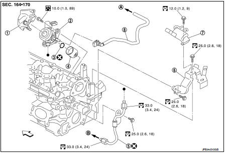
1. High pressure fuel pump insulator
2. High pressure fuel pump
3. O-ring
4. Valve lifter
5. Fuel tube assembly
6. Bracket
7. Fuel pump connector protector
8. Fuel feed hose
A. To centralized under-floor piping B. To fuel tube assembly
 : Engine front
 : N┬Ęm (kg-m, ft-lb)
 : N┬Ęm (kg-m, in-lb)
 : Always replace after every
disassembly.
Removal and Installation
REMOVAL
WARNING:
ŌĆó Be sure to read EM-7, "Precaution for Handling High Pressure Fuel System" when
working on the
high pressure fuel system.
ŌĆó Put a ŌĆ£CAUTION: FLAMMABLEŌĆØ sign in the workshop.
ŌĆó Be sure to work in a well ventilated area and furnish workshop with a CO2 fire extinguisher.
ŌĆó Never smoke while servicing fuel system. Keep open flames and sparks away from the work area.
ŌĆó To avoid the danger of being scalded, never drain engine coolant when engine is hot.
1. Release fuel pressure. Refer to EC-140, "Work Procedure".
2. Remove engine cover. Refer toEM-25, "Exploded View".
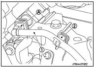
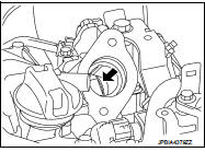
3. Remove fuel pump connector protector, and remove high pressure fuel pump insulator.
4. Disconnect harness connector (A) with the following procedure.
a. Disconnect fuel feed hose (1) from clamp (2).
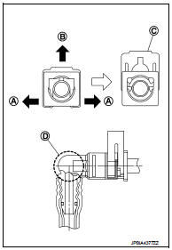
b. Disengage (A) and pull up (B) the pawl of the fuel feed hose conector retainer (C) to disconnect the fuel feed tube from high pressure fuel pump.
NOTE
:
If the fuel feed hose is stuck, hold the fuel pipe by hand and disconnect
it by pusing and pulling.
CAUTION:
ŌĆó Keep parts away from heat source. Especially, be careful
when welding is performed around them.
ŌĆó Never expose parts to battery electrolyte or other acids.
ŌĆó Never bent or twist connection between quick connector and fuel feed hose (with damper) during installation/ removal.
ŌĆó Pull quick connector holding (D).
ŌĆó Do not remove the retainer.
ŌĆó Prepare container and colth beforehand as fuel will leak out.
ŌĆó Never pull with lateral force applied. O-ring inside quick connector may be damaged.
Retainer color : Red
ŌĆó To keep clean the connecting portion and to avoid damage and foreign materials, cover them completely with plastic bags (A), etc. or a similar item.
5. Remove intake manifold. Refer to EM-29, "Removal and Installation".
6. Remove fuel feed tube.
7. Remove high pressure fuel pump and lifter.
INSTALLATION
1. Install high pressure pump with the following procedure.
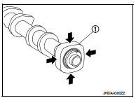
a. Check the orientation of oil pump cam from the mounting area (view arrow) of high pressure fuel pump.
b. Aim oil pump cam at the BTC area (arrow position).
1 : Camshaft (EXH)
NOTE
:
For BTC area, anywhere whithin the area indicated by arrow can
be accepted.
c. Install O-ring to high pressure fuel pump. When handing new O-ring, paying
attention to the following caution
items:
CAUTION:
ŌĆó Handle O-ring with bare hands. Never wear gloves.
ŌĆó Lubricate O-ring with new engine oil.
ŌĆó Never clean O-ring with solvent.
ŌĆó Check that O-ring and its mating part are free of foreign material.
ŌĆó When installing O-ring, be careful not to scratch it with tool or fingernails. Also be careful not to twist or stretch O-ring. If O-ring was stretched while it was being attached, never insert it quickly into fuel tube.
ŌĆó Insert new O-ring straight into fuel rail. Never decenter or twist it.
d. Install valve lifter.
e. Apply oil to the fitting area of high pressure O-ring and cam shaft bracket side to install high pressure pump.
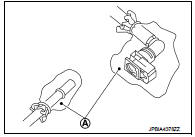
2. Connect fuel feed hose with the following procedure, and them install the fuel feed hose.
a. Check no foreign substances are deposited in and around matching pipe and quick connector.
b. Quick connector shall be inserted gradually, aligning with the axis of the matching pipe.
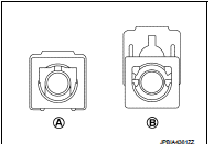
c. Insert the retainer until it clicks and check the retainer is locked.
After insertion, pull the connector and check that the connector is locked.
A : Lock position
B : Unlock position
CAUTION: If retainer cannot be installed smoothly, quick connector may be have not been installed correctly. Check connection again.
d. After attaching the quick connector and fix the hose to the clamp.
3. Install in the reverse order of removal after this step.
Inspection
INSPECTION AFTER INSTALLATION
Check for Fuel Leakage 1. Turn ignition switch ŌĆ£ONŌĆØ (with the engine stopped). With fuel pressure applied to fuel piping, check that there is no fuel leakage at connection points.
NOTE:
Use mirrors for checking at points out of clear sight.
2. Start the engine. With engine speed increased, check again that there is no fuel leakage at connection points.
CAUTION:
Never touch the engine immediately after it is stopped because the engine is
extremely hot.
 Oil pan (lower)
Exploded View
1. O-ring
2. Oil pan (upper)
3. Oil level gauge guide
4. O-ring
5. Oil level gauge
6. Oil pump drive chain
7. Crankshaft sprocket
8. Oil pump sprocket
9. Oil pump chain ...
 Fuel injector and fuel tube
Exploded View
1. Holder
2. Seal ring (white)
3. Backup ring
4. O-ring (blue)
5. Fuel injector
6. Stud bolt
7. Fuel tube assembly
8. Fuel tube insulator
9. Fuel tube protector
10. Fu ...
Other materials:
Front disc brake
Brake pad : Exploded View
MR16DDT
1. Cylinder body
2. Inner shim
3. Inner pad (with pad wear sensor)
4. Pad retainer
5. Torque member
6. Outer pad
7. Outer shim
1: Apply MOLYKOTE® AS880N or
silicone-based grease.
2: Apply MOLYKOTE® 7439 or
equivalent.
: N┬Ęm (kg-m, ft-lb)
HR1 ...
Information display (ASCD)
Component Function Check
1.CHECK INFORMATION DISPLAY
1. Start engine.
2. Press ASCD MAIN switch.
3. Drive the vehicle at more than 30 km/h (20 MPH)
CAUTION:
Always drive vehicle at a safe speed.
4. Press SET/ACCELERATE or SET/COAST switch.
5. Check that the readings of the speedometer show t ...
C1101, C1102, C1103, C1104 wheel sensor
DTC Logic
DTC DETECTION LOGIC
DTC CONFIRMATION PROCEDURE
1.PRECONDITIONING
If ŌĆ£DTC CONFIRMATION PROCEDUREŌĆØ has been previously conducted, always turn
ignition switch OFF and
wait at least 10 seconds before conducting the next test.
>> GO TO 2.
2.CHECK DTC DETECTION
With CON ...
