Nissan Juke Service and Repair Manual : Oil pan (lower)
Exploded View
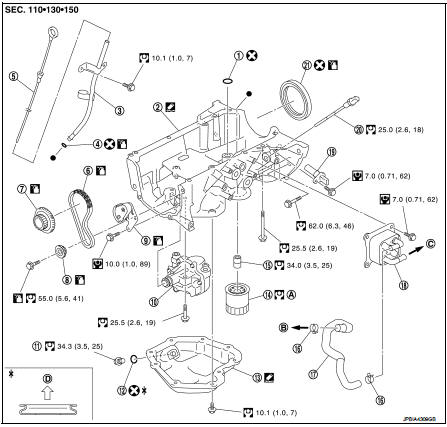
1. O-ring
2. Oil pan (upper)
3. Oil level gauge guide
4. O-ring
5. Oil level gauge
6. Oil pump drive chain
7. Crankshaft sprocket
8. Oil pump sprocket
9. Oil pump chain tensioner
10. Oil pump
11. Drain plug
12. Drain plug washer
13. Oil pan (lower)
14. Oil filter
15. Connector bolt
16. Clamp
17. Water hose
18. Oil cooler
19. Crankshaft position sensor
20. Oil level sensor
21. Rear oil seal
A. Refer to LU-11
B. Oil pan side
C. To thermostat housing (M/T models)
To CVT oil warmer (CVT models)
D. Oil pan side
 : N·m (kg-m, ft-lb)
 : N·m (kg-m, in-lb)
 : Always replace after every
disassembly.
 : Sealing point
 : Should be lubricated with oil.
Removal and Installation
1. Drain engine oil. Refer to LU-9, "Draining".
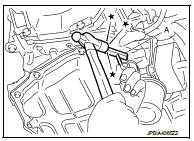
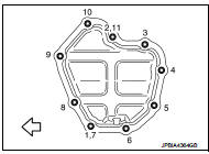
2. Remove oil pan (lower) with the following procedure: a. Loosen mounting bolts in reverse order as shown in the figure.
 : Engine front
NOTE:
Disregard the numerical order No.7 and No.11 in removal.
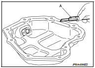
![b. Insert seal cutter [SST: KV10111100 (J-37228)] (A) between oil](images/books/335/2/index.87.jpg)
b. Insert seal cutter [SST: KV10111100 (J-37228)] (A) between oil pan (upper) and oil pan (lower).
CAUTION:
• Be careful not to damage the mating surface.
• Never insert a screwdriver. This damages the mating surfaces.
c. Slide the seal cutter [SST: KV10111100 (J-37228)] by tapping on the side of tool with a hammer.
d. Remove oil pan (lower).
INSTALLATION
1. Install oil pan (lower) as follows: a. Use a scraper (A) to remove old liquid gasket from mating surfaces.
• Also remove old liquid gasket from mating surface of oil pan (upper).
• Remove old liquid gasket from the bolt holes and threads.
CAUTION:
Never scratch or damage the mating surface when cleaning
off old liquid gasket.
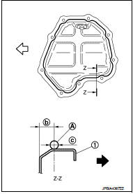
b. Apply a continuous bead of liquid gasket (A) with a tube presser (commercial service tool) as shown in the figure.
1 : Oil pan (lower)
b : 7.5-9.5mm (0.295 - 0.374 in)
c : φ 4.0 - 5.0 mm (0.157 - 0.197 in)
 : Engine outside
Use Genuine Liquid Gasket or equivalent.
CAUTION:
Attaching should be done within 5 minutes after liquid gasket
application.
c. Tighten bolts in numerical order as shown in the figure.
: Engine front
NOTE
:
• Tighten bolts the No.1 and No.2 in two steps.
• The numerical order No.7 and No.11 shows the second steps.
2. Install oil pan drain plug.
• Refer to the figure of components of former page for installation direction of drain plug washer. Refer to EM-99, "Exploded View".
3. Install in the reverse order of removal after this step.
Inspection
INSPECTION AFTER REMOVAL
Clean oil strainer if any object attached.
INSPECTION AFTER INSTALLATION
1. Check the engine oil level and adjust engine oil. Refer to LU-8, "Inspection".
2. Start engine, and check there is no leakage of engine oil.
3. Stop engine and wait for 10 minutes.
4. Check the engine oil level again. Refer to LU-8, "Inspection".
 Exhaust manifold
Exploded View
1. Stud bolt
2. Exhaust manifold cover
3. Exhaust manifold
4. Gasket
Engine front
: N·m (kg-m, ft-lb)
: N·m (kg-m, in-lb)
: Always replace after every
disassembly.
Remo ...
 High pressure fuel pump and fuel hose
Exploded View
CAUTION:
Never remove or disassemble parts unless instructed as shown in the figure.
1. High pressure fuel pump insulator
2. High pressure fuel pump
3. O-ring
4. Valve lifter ...
Other materials:
Door switch
Component Function Check
1.CHECK FUNCTION
1. Select “DOOR LOCK” of “BCM” using CONSULT-III.
2. Select “DOOR SW-DR”, “DOOR SW-AS”, “DOOR SW-RL”, “DOOR SW-RR”, “DOOR SW-BK”
in “DATA
MONITOR” mode.
3. Check that the function operates normally according to the fo ...
P0500 VSS
Description
The vehicle speed signal is sent to the combination meter from the “ABS
actuator and electric unit (control
unit)” by CAN communication line. The combination meter then sends a signal to
the ECM by CAN communication
line.
DTC Logic
DTC DETECTION LOGIC
NOTE:
• If DTC P050 ...
Headlamp aiming switch
Exploded View
1. Headlamp aiming switch
2. Instrument lower panel assembly LH
: Pawl
Removal and Installation
REMOVAL
1. Remove instrment lower panel (LH/RH). Refer to IP-13, "Removal and
Installation".
2. Remove headlamp aiming switch fixing clips, and then remove headlamp aim ...
