Nissan Juke Service and Repair Manual : Exhaust manifold
Exploded View
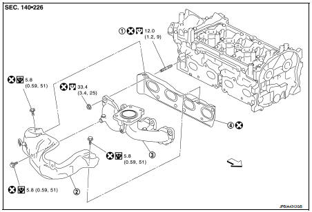
1. Stud bolt
2. Exhaust manifold cover
3. Exhaust manifold
4. Gasket
 Engine front
 : N·m (kg-m, ft-lb)
 : N·m (kg-m, in-lb)
 : Always replace after every
disassembly.
Removal and Installation
REMOVAL
1. Drain engine coolant. Refer to CO-11, "Draining".
2. Remove turbocharger. Refer to EM-36, "Exploded View".
3. Remove catalyst convertor. Refer to EM-33, "2WD : Exploded View" (2WD models) or EM-34, "4WD : Exploded View" (4WD models).
4. Remove exhaust manifold cover.
5. Remove exhaust manifold.
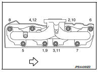
• Loosen nuts in reverse order as shown in the figure.
 : Engine front
NOTE:
Disregard the numerical order No. 9 to 12 in removal.
6. Remove gasket.
CAUTION:
Cover engine openings to avoid entry of foreign materials.
INSTALLATION
1. Install gasket to cylinder head as shown in the figure.
: Engine front
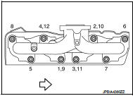
2. Install exhaust manifold with the following procedure: a. Tighten nuts in numerical order as shown in the figure.
: Engine front
NOTE
:
• Tighten nuts the No.1 to No.4 in two steps.
• The numerical order No.9 to No.12 shows the second step.
3. Install remaining parts in the reverse order of removal.
Inspection
INSPECTION AFTER REMOVAL
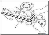
Surface Distortion
• Using feeler gauge (A) and straightedge (B), check the surface distortion
of exhaust manifold mating surface in each exhaust port
and entire part.
Limit : Refer to EM-130, "Exhaust Manifold".
• If it exceeds the limit, replace exhaust manifold.
 Turbocharger
Exploded View
1. Heat insulator
2. Actuator hose
3. Clamp
4. Turbocharger inlet tube
5. Gasket
6. Gasket
7. Clamp
8. Oil outlet hose
9. Oil return pipe
10. Oil supply tube
11. O-ri ...
 Oil pan (lower)
Exploded View
1. O-ring
2. Oil pan (upper)
3. Oil level gauge guide
4. O-ring
5. Oil level gauge
6. Oil pump drive chain
7. Crankshaft sprocket
8. Oil pump sprocket
9. Oil pump chain ...
Other materials:
P0112, P0113 IAT SENSOR
DTC Logic
DTC DETECTION LOGIC
DTC CONFIRMATION PROCEDURE
1.PRECONDITIONING
If DTC Confirmation Procedure has been previously conducted, always turn
ignition switch OFF and wait at
least 10 seconds before conducting the next test.
>> GO TO 2.
2.PERFORM DTC CONFIRMATION PROCEDURE
...
Front wheel hub and knuckle
Inspection
COMPONENT PART
Check that the mounting conditions (looseness, backlash) of each component
and component conditions
(wear, damage) are normal.
WHEEL HUB ASSEMBLY (BEARING-INTEGRATED TYPE)
Check the following items, and replace the part if necessary.
• Move wheel hub assembly ...
Door request switch
Component Function Check
1.CHECK FUNCTION
1. Select “INTELLIGENT KEY” of “BCM” using CONSULT-III.
2. Select “REQ SW-DR”, “REQ SW-AS” in “DATA MONITOR” mode.
3. Check that the function operates normally according to the following
conditions.
Is the inspection result norma ...
