Nissan Juke Service and Repair Manual : Turbocharger
Exploded View
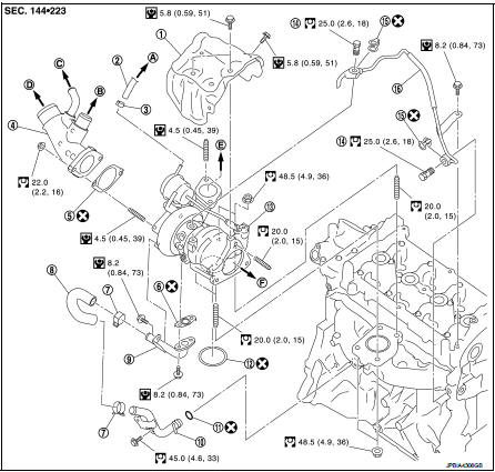
1. Heat insulator
2. Actuator hose
3. Clamp
4. Turbocharger inlet tube
5. Gasket
6. Gasket
7. Clamp
8. Oil outlet hose
9. Oil return pipe
10. Oil supply tube
11. O-ring
12. O-ring
13. Turbocharger
14. Eye bolt
15. Gasket
16. Oil supply tube
A. To EVAP canister purge volume control
solenoid valve
B. To air inlet hose
C. To PCV hose
D. To air duct E. To air inlet tube assembly F. To catalyst convertor
 : N·m (kg-m, ft-lb)
 : N·m (kg-m, in-lb)
 : Always replace after every
disassembly.
Removal and Installation
REMOVAL
1. Drain engine coolant. Refer to CO-11, "Draining".
2. Remove engine cover. Refer to EM-25, "Exploded View".
3. Remove air cleaner cover assembly and air cleaner body assembly. Refer to EM-26, "Exploded View".
4. Remove air inlet tube assembly. Refer to EM-31, "Exploded View".
5. Remove cowl top extension. Refer to EXT-20, "Exploded View".
6. Disconnect heated oxygen sensor 2 harness connector.
7. Remove front tube. Refer to EX-5, "Exploded View".
8. Remove catalyst convertor. Refer to EM-33, "2WD : Exploded View" (2WD models) or EM-34, "4WD : Exploded View" (4WD models).
9. Remove turbocharger assembly as follows:
a. Remove heat insulator.
b. Remove oil supply tube.
c. Remove mounting nuts of turbocharger.
CAUTION:
Be careful not to deform each turbocharger piping when pulling out the assembly.
INSTALLATION
Install in the reverse order of removal.
NOTE
:
Apply LOCTITE FRENETANCH or equivalent to the threads of the turbocharger oil inlet pipe union to the cylinder head
Inspection
Turbocharger
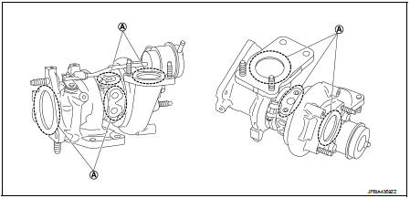
A. Check for leakage
CAUTION:
When the compressor wheel, turbine wheel or rotor shaft is damaged, remove all
the fragments and
foreign matter left in the following passages in order to prevent a secondary
failure:
Suction side : Between turbocharger and air cleaner Exhaust side : Between turbocharger and outlet duct
INSPECTION AFTER INSTALLATION
Start engine and raise engine speed to check no exhaust emission leaks.
 Catalyst
2WD
2WD : Exploded View
1. A/F sensor 1
2. Catalyst convertor shroud upper
3. Gasket
4. Catalyst
5. Catalyst convertor support bracket rear
6. Catalyst convertor bracket (RH)
A. To exhau ...
 Exhaust manifold
Exploded View
1. Stud bolt
2. Exhaust manifold cover
3. Exhaust manifold
4. Gasket
Engine front
: N·m (kg-m, ft-lb)
: N·m (kg-m, in-lb)
: Always replace after every
disassembly.
Remo ...
Other materials:
B210D starter relay
DTC Logic
DTC DETECTION LOGIC
NOTE:
• If DTC B210D is displayed with DTC U1000, first perform the trouble diagnosis
for DTC U1000. Refer to
PCS-59, "DTC Logic".
• If DTC B210D is displayed with DTC B209F, first perform the trouble diagnosis
for DTC B209F. Refer to
SEC-209, &q ...
System
Can communication system
CAN COMMUNICATION SYSTEM : System Diagram
CAN COMMUNICATION SYSTEM : System Description
Description
• CAN (Controller Area Network) is a serial communication line for real time
application. It is an on-vehicle
multiplex communication line with high data communicat ...
Door lock status indicator
Component Function Check
1.CHECK FUNCTION
1. Select “DOOR LOCK” of “BCM” using CONSULT-III.
2. Select “DOOR LOCK IND” in “ACTIVE TEST” mode.
3. Check that the function operates normally according to the following
conditions.
Is the inspection result normal?
YES >> Doo ...
