Nissan Juke Service and Repair Manual : Diagnosis system (BCM)
Common item
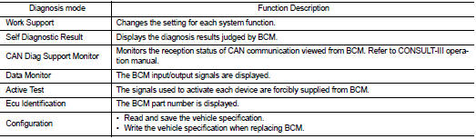
COMMON ITEM : CONSULT-III Function (BCM - COMMON ITEM)
APPLICATION ITEM
CONSULT-III performs the following functions via CAN communication with BCM.
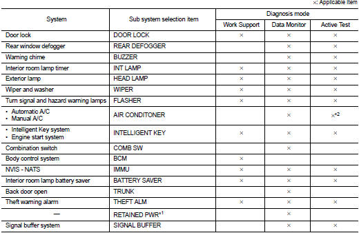
SYSTEM APPLICATION
BCM can perform the following functions for each system.
NOTE
:
It can perform the diagnosis modes except the following for all sub system
selection items.
NOTE
:
• *1: This item is displayed, but not used.
• *2: For models with automatic A/C, this diagnosis mode is not used.
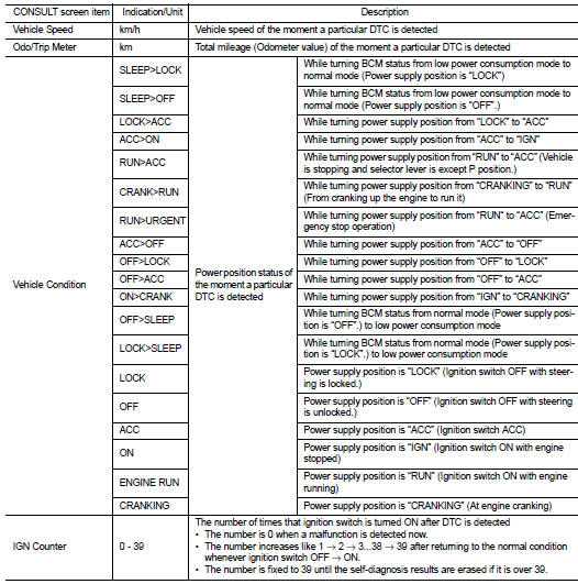
FREEZE FRAME DATA (FFD)
The BCM records the following vehicle condition at the time a particular DTC is detected, and displays on CONSULT-III.
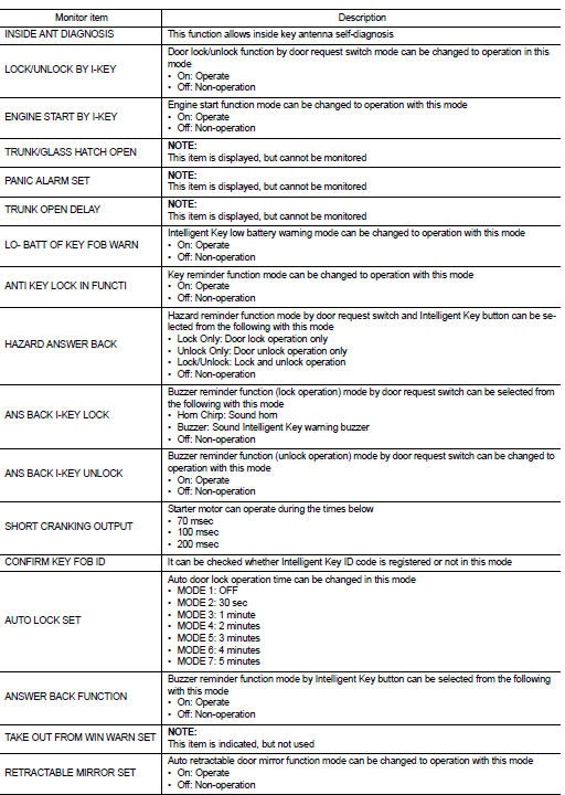
Intelligent key
INTELLIGENT KEY : CONSULT-III Function (BCM - INTELLIGENT KEY) (With Super Lock)
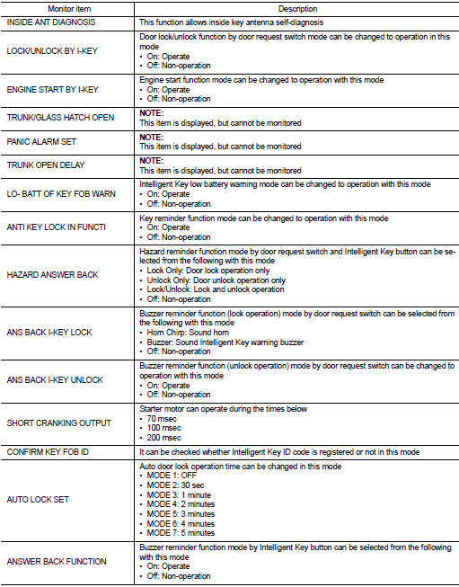
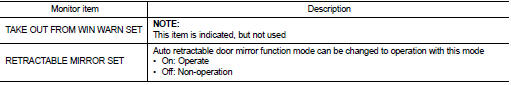
WORK SUPPORT
SELF-DIAG RESULT
Refer to BCS-67, "DTC Index".
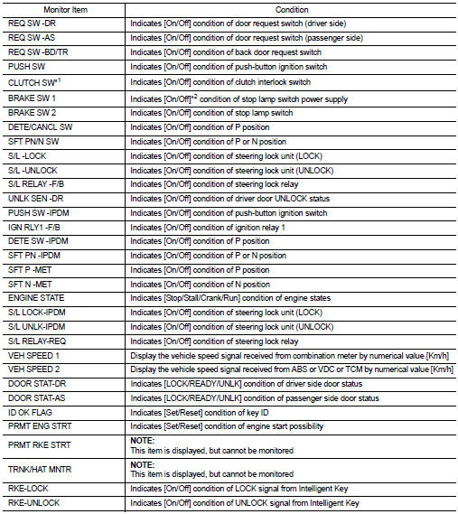
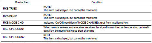
DATA MONITOR
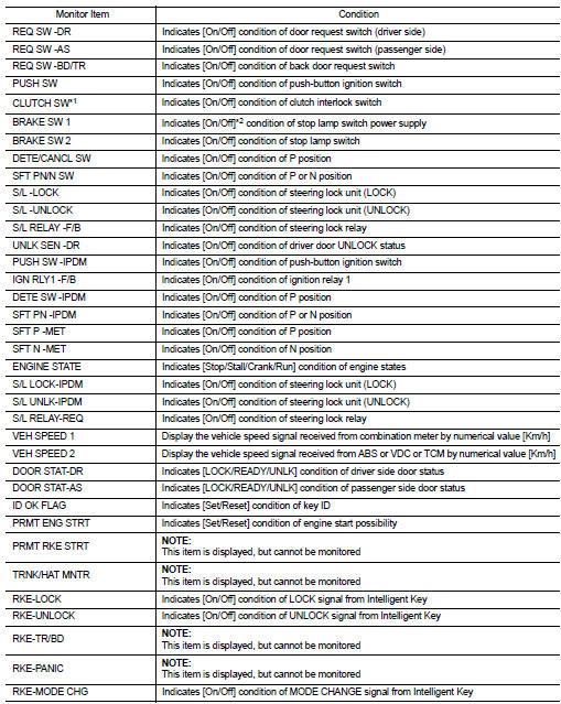
*1: It is displayed but does not operate on CVT models.
*2: OFF is displayed when brake pedal is depressed while brake switch power supply is OFF.
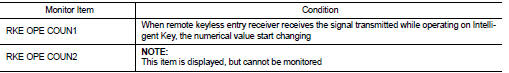
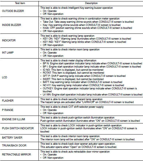
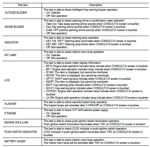
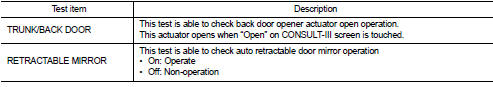
ACTIVE TEST
INTELLIGENT KEY : CONSULT-III Function (BCM - INTELLIGENT KEY) (Without Super Lock)
WORK SUPPORT
SELF-DIAG RESULT
Refer to BCS-67, "DTC Index".
DATA MONITO
*1: It is displayed but does not operate on CVT models.
*2: OFF is displayed when brake pedal is depressed while brake switch power supply is OFF.
ACTIVE TEST
 System
POWER DISTRIBUTION SYSTEM
POWER DISTRIBUTION SYSTEM : System Description
SYSTEM DESCRIPTION
• PDS (POWER DISTRIBUTION SYSTEM) is the system that BCM controls with the
operation of the pushbutto ...
 ECU diagnosis information
BCM
List of ECU Reference
...
Other materials:
System
CVT control system : System Diagram
CVT control system : System Description
The CVT senses vehicle operating conditions through various sensors. It
always controls the optimum shift
position and reduces shifting and lock-up shocks.
TCM FUNCTION
The function of the TCM is to:
• Receive ...
Rear bumper
Exploded View
1. Bumper side bracket LH
2. Bumper closing LH
3. Bumper fascia assembly
4. Reflex reflector LH
5. Rear panel lower
6. U nut
7. Bumper fascia lower
8. Reflex reflector RH
9. Bumper stay LH
10. screw grommet
11. Bumper energy absorber
12. Bumper stay RH
13. Bumper ...
C1121, C1123, C1125, C1127 ABS out valve system
DTC Logic
DTC DETECTION LOGIC
wait at least 10 seconds before conducting the next test.
>> GO TO 2.
2.CHECK DTC DETECTION
With CONSULT-III
1. Turn the ignition switch OFF to ON.
2. Perform self-diagnosis for “ABS”.
Is DTC “C1121”, “C1123”, “C1125” or “C1127” ...
