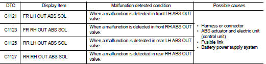
Nissan Juke Service and Repair Manual : C1121, C1123, C1125, C1127 ABS out valve system
DTC Logic
DTC DETECTION LOGIC
wait at least 10 seconds before conducting the next test.
>> GO TO 2.
2.CHECK DTC DETECTION
 With CONSULT-III
1. Turn the ignition switch OFF to ON.
2. Perform self-diagnosis for ŌĆ£ABSŌĆØ.
Is DTC ŌĆ£C1121ŌĆØ, ŌĆ£C1123ŌĆØ, ŌĆ£C1125ŌĆØ or ŌĆ£C1127ŌĆØ detected? YES >> Proceed to BRC-181, "Diagnosis Procedure".
NO >> INSPECTION END
Diagnosis Procedure
1.CHECK CONNECTOR
1. Turn the ignition switch OFF.
2. Check ABS actuator and electric unit (control unit) harness connector for disconnection or looseness.
Is the inspection result normal? YES >> GO TO 3.
NO >> Repair or replace error-detected parts, securely lock the connector, and GO TO 2.
2.PERFORM SELF-DIAGNOSIS
Perform self-diagnosis for ŌĆ£ABSŌĆØ again.
Is DTC ŌĆ£C1121ŌĆØ, ŌĆ£C1123ŌĆØ, ŌĆ£C1125ŌĆØ or ŌĆ£C1127ŌĆØ detected? YES >> GO TO 3.
NO >> INSPECTION END
3.CHECK ABS OUT VALVE POWER SUPPLY
1. Turn the ignition switch OFF.
2. Disconnect ABS actuator and electric unit (control unit) harness connector.
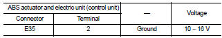
3. Check voltage between ABS actuator and electric unit (control unit) harness connector and ground.
4. Turn the ignition switch ON.
CAUTION:
Never start engine.
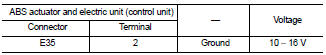
5. Check voltage between ABS actuator and electric unit (control unit) harness connector and ground.
Is the inspection result normal? YES >> GO TO 5.
NO >> GO TO 4.
4.CHECK ABS OUT VALVE POWER SUPPLY CIRCUIT
1. Turn the ignition switch OFF.
2. Check 50 A fusible link (I).
3. Check continuity and short circuit between ABS actuator and electric unit (control unit) harness connector terminal (2) and 50 A fusible link (I).
Is the inspection result normal? YES >> Perform trouble diagnosis for battery power supply. Refer to PG-10, "Wiring Diagram - BATTERY POWER SUPPLY -".
NO >> Repair or replace error-detected parts.
5.CHECK ABS OUT VALVE GROUND CIRCUIT
1. Turn the ignition switch OFF.
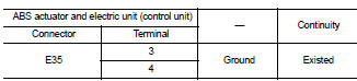
2. Check continuity between ABS actuator and electric unit (control unit) harness connector and the ground.
Is the inspection result normal? YES >> GO TO 6.
NO >> Repair or replace error-detected parts.
6.CHECK TERMINAL
Check ABS actuator and electric unit (control unit) pin terminals for damage or loose connection with harness connector.
Is the inspection result normal? YES >> Replace ABS actuator and electric unit (control unit). Refer to BRC-233, "Removal and Installation".
NO >> Repair or replace error-detected parts.
 C1120, C1122, C1124, C1126 ABS in valve system
DTC Logic
DTC DETECTION LOGIC
DTC CONFIRMATION PROCEDURE
1.PRECONDITIONING
If ŌĆ£DTC CONFIRMATION PROCEDUREŌĆØ has been previously conducted, always turn
ignition switch OFF and
wait at least ...
 C1130 engine signal
DTC Logic
DTC DETECTION LOGIC
DTC CONFIRMATION PROCEDURE
1.PRECONDITIONING
If ŌĆ£DTC CONFIRMATION PROCEDUREŌĆØ has been previously conducted, always turn
ignition switch OFF and
wait at least ...
Other materials:
4WD warning lamp does not turn off
Description
4WD warning lamp does not turn OFF several seconds after the engine started.
Diagnosis Procedure
1.PERFORM SELF-DIAGNOSIS
With CONSULT-III
Perform self-diagnosis for ŌĆ£ALL MODE AWD/4WDŌĆØ.
Is any DTC detected?
YES >> Check the DTC. Refer to DLN-33, "DTC Index".
...
A/C on signal
Component Function Check
1.CHECK A/C ON SIGNAL
With CONSULT-III
1. Turn ignition switch ON.
2. Operate blower motor.
3. Select ŌĆ£AIR CONDITIONERŌĆØ of ŌĆ£BCMŌĆØ using CONSULT-III.
4. Select ŌĆ£AIR COND SWŌĆØ in ŌĆ£DATA MONITORŌĆØ mode.
5. Check A/C ON signal when the A/C switch is operated.
...
Tire labeling
Federal law requires tire manufacturers to place standardized information on
the sidewall of all tires. This information identifies and describes the fundamental
characteristics of the tire and also provides the tire identification number (TIN)
for safety standard certification. The TIN can be ...
