Nissan Juke Service and Repair Manual : C1120, C1122, C1124, C1126 ABS in valve system
DTC Logic
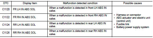
DTC DETECTION LOGIC
DTC CONFIRMATION PROCEDURE
1.PRECONDITIONING
If ŌĆ£DTC CONFIRMATION PROCEDUREŌĆØ has been previously conducted, always turn ignition switch OFF and wait at least 10 seconds before conducting the next test.
>> GO TO 2.
2.CHECK DTC DETECTION
 With CONSULT-III
1. Turn the ignition switch OFF to ON.
2. Perform self-diagnosis for ŌĆ£ABSŌĆØ.
Is DTC ŌĆ£C1120ŌĆØ, ŌĆ£C1122ŌĆØ, ŌĆ£C1124ŌĆØ or ŌĆ£C1126ŌĆØ detected? YES >> Proceed to BRC-179, "Diagnosis Procedure".
NO >> INSPECTION END
Diagnosis Procedure
1.CHECK CONNECTOR
1. Turn the ignition switch OFF.
2. Check ABS actuator and electric unit (control unit) harness connector for disconnection or looseness.
Is the inspection result normal? YES >> GO TO 3.
NO >> Repair or replace error-detected parts, securely lock the connector, and GO TO 2.
2.PERFORM SELF-DIAGNOSIS
Perform self-diagnosis for ŌĆ£ABSŌĆØ again.
Is DTC ŌĆ£C1120ŌĆØ, ŌĆ£C1122ŌĆØ, ŌĆ£C1124ŌĆØ or ŌĆ£C1126ŌĆØ detected? YES >> GO TO 3.
NO >> INSPECTION END
3.CHECK ABS IN VALVE POWER SUPPLY
1. Turn the ignition switch OFF.
2. Disconnect ABS actuator and electric unit (control unit) harness connector.
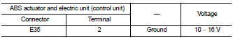
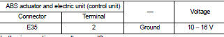
3. Check voltage between ABS actuator and electric unit (control unit) harness connector and ground.
4. Turn the ignition switch ON.
CAUTION:
Never start engine.
5. Check voltage between ABS actuator and electric unit (control unit) harness connector and ground.
Is the inspection result normal? YES >> GO TO 5.
NO >> GO TO 4.
4.CHECK ABS IN VALVE POWER SUPPLY CIRCUIT
1. Turn the ignition switch OFF.
2. Check 50 A fusible link (I).
3. Check continuity and short circuit between ABS actuator and electric unit (control unit) harness connector terminal (2) and 50 A fusible link (I).
Is the inspection result normal? YES >> Perform trouble diagnosis for battery power supply. Refer to PG-10, "Wiring Diagram - BATTERY POWER SUPPLY -".
NO >> Repair or replace error-detected parts.
5.CHECK ABS IN VALVE GROUND CIRCUIT
1. Turn the ignition switch OFF.
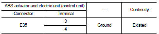
2. Check continuity between ABS actuator and electric unit (control unit) harness connector and the ground.
Is the inspection result normal? YES >> GO TO 6.
NO >> Repair or replace error-detected parts.
6.CHECK TERMINAL
Check ABS actuator and electric unit (control unit) pin terminals for damage or loose connection with harness connector.
Is the inspection result normal? YES >> Replace ABS actuator and electric unit (control unit). Refer to BRC-233, "Removal and Installation".
NO >> Repair or replace error-detected parts.
 C1116 stop lamp switch
DTC Logic
DTC DETECTION LOGIC
DTC CONFIRMATION PROCEDURE
1.PRECONDITIONING
If ŌĆ£DTC CONFIRMATION PROCEDUREŌĆØ has been previously conducted, always turn
ignition switch OFF and
wait at least ...
 C1121, C1123, C1125, C1127 ABS out valve system
DTC Logic
DTC DETECTION LOGIC
wait at least 10 seconds before conducting the next test.
>> GO TO 2.
2.CHECK DTC DETECTION
With CONSULT-III
1. Turn the ignition switch OFF to ON.
2. ...
Other materials:
C1142 press sensor
DTC Logic
DTC DETECTION LOGIC
DTC CONFIRMATION PROCEDURE
1.PRECONDITIONING
If ŌĆ£DTC CONFIRMATION PROCEDUREŌĆØ has been previously conducted, always turn
ignition switch OFF and
wait at least 10 seconds before conducting the next test.
>> GO TO 2.
2.CHECK DTC DETECTION
With CON ...
Component parts
Component Parts Location
1. BCM
Refer to BCS-6, "BODY CONTROL
SYSTEM : Component Parts Location"
(with Intelligent Key) or BCS-96,
"BODY CONTROL SYSTEM : Component
Parts Location" (without Intelligent
Key)
2. Power window main switch
3. Front power window motor (drive ...
Inspection
OIL LEAKAGE
Make sure that gear oil is not leaking from transaxle or around it.
OIL LEVEL
1. Remove filler plug (1) and gasket from transaxle case.
2. Check the oil level from filler plug mounting hole as shown in the
figure.
CAUTION:
Never start engine while checking oil level.
3. Set a ...
