Nissan Juke Service and Repair Manual : A/C on signal
Component Function Check
1.CHECK A/C ON SIGNAL
 With CONSULT-III
1. Turn ignition switch ON.
2. Operate blower motor.
3. Select “AIR CONDITIONER” of “BCM” using CONSULT-III.
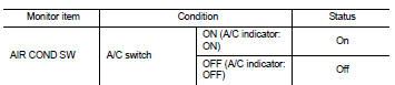
4. Select “AIR COND SW” in “DATA MONITOR” mode.
5. Check A/C ON signal when the A/C switch is operated.
Is the inspection result normal? YES >> INSPECTION END
NO >> Refer to HAC-166, "Diagnosis Procedure".
Diagnosis Procedure
1.CHECK A/C ON SIGNAL
1. Turn ignition switch OFF.
2. Disconnect A/C auto amp. connector.
3. Turn ignition switch ON.
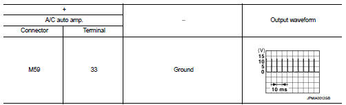
4. Check output waveform between A/C auto amp. harness connector and ground with using oscilloscope.
Is the inspection result normal? YES >> Replace A/C auto amp. Refer to HAC-188, "Removal and Installation".
NO >> GO TO 2.
2.CHECK A/C ON SIGNAL CIRCUIT FOR OPEN
1. Turn ignition switch OFF.
2. Disconnect BCM connector.
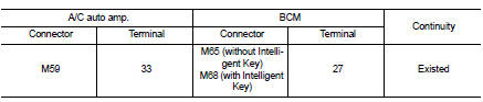
3. Check continuity between A/C auto amp. harness connector and BCM harness connector.
Is the inspection result normal? YES >> GO TO 3.
NO >> Repair harness or connector.
3.CHECK A/C ON SIGNAL CIRCUIT FOR SHORT
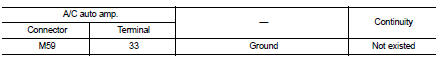
Check continuity between A/C auto amp. harness connector and ground.
Is the inspection result normal? YES >> Replace BCM. Refer to BCS-93, "Removal and Installation" (with Intelligent Key) or BCS-161, "Removal and Installation" (without Intelligent Key).
NO >> Repair harness or connector.
 Door motor
Diagnosis Procedure
NOTE:
If all of door motor DTCs are detected, check this circuit.
1.CHECK DOOR MOTOR POWER SUPPLY
1. Turn ignition switch ON.
2. Check voltage between intake door motor harn ...
 Blower fan on signal
Component Function Check
1.CHECK BLOWER FAN ON SIGNAL
With CONSULT-III
1. Turn ignition switch ON.
2. Select “AIR CONDITIONER” of “BCM” using CONSULT-III.
3. Select “FAN ON SIG” in †...
Other materials:
Intelligent Cruise Control (ICC) (for vehicles with ProPILOT Assist)
WARNING
Failure to strictly adhere to these warnings and operational instructions regarding the Intelligent Cruise Control (ICC) system in your Nissan Leaf could result in a serious accident, personal injury, or death.
The ICC system is strictly a driver-assistance aid; it is not ...
Immediate charge
When you haven't enabled a charging timer, your Nissan Leaf is designed to begin charging automatically the moment you connect a normal or trickle charge connector to the vehicle's charge port. This ensures the most straightforward and rapid replenishment of your battery.
However, even if you h ...
Inside key antenna
Instrument center
INSTRUMENT CENTER : Removal and Installation
REMOVAL
1. Remove the multi display unit. Refer to AV-125, "Removal and
Installation".
2. Remove the inside key antenna (instrument center) (1) mounting
clip (A), and then remove inside key antenna (instrument
center).
...
