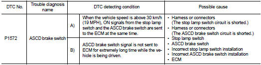
Nissan Juke Service and Repair Manual : P1572 ASCD brake switch
DTC Logic
DTC DETECTION LOGIC
NOTE
:
ŌĆó If DTC P1572 is displayed with DTC P0605, first perform the trouble diagnosis
for DTC P0605. Refer
to EC-683, "DTC Logic".
ŌĆó This self-diagnosis has the one trip detection logic. When malfunction A is detected, DTC is not stored in ECM memory. And in that case, 1st trip DTC and 1st trip freeze frame data are displayed.
1st trip DTC is erased when ignition switch is turned OFF. And even when malfunction A is detected in two consecutive trips, DTC is not stored in ECM memory.
DTC CONFIRMATION PROCEDURE
1.PRECONDITIONING
If DTC Confirmation Procedure has been previously conducted, always turn ignition switch OFF and wait at least 10 seconds before conducting the next page.
NOTE: The procedure for malfunction B is not described. It takes an extremely long time to complete the procedure for malfunction B. By performing the procedure for malfunction A, the condition that causes malfunction B can be detected.
>> GO TO 2.
2.PERFORM DTC CONFIRMATION PROCEDURE-I
1. Start engine (ESP switch OFF).
2. Select ŌĆ£ENGINEŌĆØ using CONSULT-III.
3. Select ŌĆ£DATA MONITORŌĆØ mode.
4. Press MAIN switch and make sure that CRUISE lamp illuminates.
5. Drive the vehicle for at least 5 consecutive seconds under the following conditions.
CAUTION:
Always drive vehicle at a safe speed.
NOTE:
This procedure may be conducted with the drive wheels lifted in the shop or by driving the vehicle.
If a road test is expected to be easier, it is unnecessary to lift the vehicle.
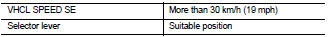
6. Check DTC.
Is DTC detected? YES >> Go to EC-718, "Diagnosis Procedure".
NO >> GO TO 3.
3.PERFORM DTC CONFIRMATION PROCEDURE-II
1. Drive the vehicle for at least 5 consecutive seconds under the following conditions.
CAUTION
:
Always drive vehicle at a safe speed.
NOTE:
This procedure may be conducted with the drive wheels lifted in the shop or by driving the vehicle.
If a road test is expected to be easier, it is unnecessary to lift the vehicle.
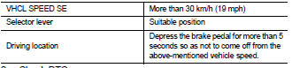
2. Check DTC.
Is DTC detected? YES >> Go to EC-718, "Diagnosis Procedure".
NO >> INSPECTION END
Diagnosis Procedure
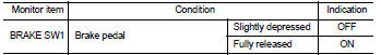
1.CHECK OVERALL FUNCTION-I
 With CONSULT-III
1. Turn ignition switch ON.
2. Select ŌĆ£ENGINEŌĆØ using CONSULT-III.
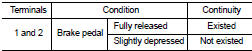
3. Select ŌĆ£BRAKE SW1ŌĆØ in ŌĆ£DATA MONITORŌĆØ mode.
4. Check ŌĆ£BRAKE SW1ŌĆØ indication under the following conditions.
 Without CONSULT-III
1. Turn ignition switch ON.
2. Check the voltage between ECM harness connector terminals as follows.
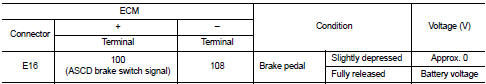
Is the inspection result normal? YES >> GO TO 2.
NO >> GO TO 3.
2.CHECK OVERALL FUNCTION-II
 With CONSULT-III
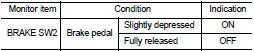
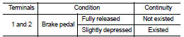
Select ŌĆ£BRAKE SW2ŌĆØ and check indication under the following conditions.
 Without CONSULT-III
Check the voltage between ECM harness connector terminals under the following conditions.
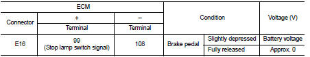
Is the inspection result normal? YES >> GO TO 11.
NO >> GO TO 7.
3.CHECK ASCD BRAKE SWITCH POWER SUPPLY CIRCUIT
1. Turn ignition switch OFF.
2. Disconnect ASCD brake switch harness connector.
3. Turn ignition switch ON.
4. Check the voltage between ASCD brake switch harness connector and ground.
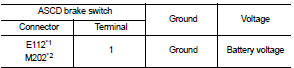
*1: LHD models or RHD models with CVT *2: RHD models with M/T
Is the inspection result normal? YES >> GO TO 5.
NO >> GO TO 4.
4.DETECT MALFUNCTIONING PART
Check the following.
ŌĆó Harness connectors E105, M77 (LHD models or RHD models with CVT)
ŌĆó Harness connectors M84, M201 (RHD models with M/T)
ŌĆó 10 A fuse (No. 3)
ŌĆó Harness for open or short between ASCD brake switch and fuse
>> Repair open circuit, short to ground or short to power in harness or connectors.
5.CHECK ASCD BRAKE SWITCH INPUT SIGNAL CIRCUIT FOR OPEN AND SHORT
1. Turn ignition switch OFF.
2. Disconnect ECM harness connector.
3. Check the continuity between ASCD brake switch harness connector and ECM harness connector.
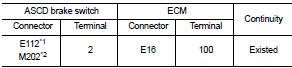
*1: LHD models or RHD models with CVT *2: RHD models with M/T
4. Also check harness for short to ground and short to power.
Is the inspection result normal? YES >> GO TO 6.
NO >> Repair open circuit, short to ground or short to power in harness or connectors.
6.CHECK ASCD BRAKE SWITCH
Refer to EC-721, "Component Inspection (ASCD Brake Switch)"
Is the inspection result normal? YES >> GO TO 11.
NO >> Replace ASCD brake switch.
7.CHECK STOP LAMP SWITCH POWER SUPPLY CIRCUIT
1. Turn ignition switch OFF.
2. Disconnect stop lamp switch harness connector.
3. Check the voltage between stop lamp switch harness connector and ground.
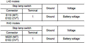
Is the inspection result normal? YES >> GO TO 9.
NO >> GO TO 8.
8.DETECT MALFUNCTIONING PART
Check the following.
ŌĆó Harness connectors E105, M77, M84, M201 (RHD models with M/T)
ŌĆó 10 A fuse (No. 38)
ŌĆó Harness for open or short between stop lamp switch and battery
>> Repair open circuit, short to ground or short to power in harness or connectors.
9.CHECK STOP LAMP SWITCH INPUT SIGNAL CIRCUIT FOR OPEN AND SHORT
1. Disconnect ECM harness connector.
2. Check the continuity between stop lamp switch harness connector and ECM harness connector.
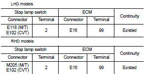
3. Also check harness for short to ground and short to power.
Is the inspection result normal? YES >> GO TO 10.
NO >> Repair open circuit, short to ground or short to power in harness or connectors.
10.CHECK STOP LAMP SWITCH
Refer to EC-721, "Component Inspection (Stop Lamp Switch)".
Is the inspection result normal? YES >> GO TO 11.
NO >> Replace stop lamp switch.
11.CHECK INTERMITTENT INCIDENT
Refer to GI-42, "Intermittent Incident".
>> INSPECTION END
Component Inspection (ASCD Brake Switch)
1.CHECK ASCD BRAKE SWITCH-I
1. Turn ignition switch OFF.
2. Disconnect ASCD brake switch harness connector.
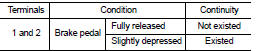
3. Check the continuity between ASCD brake switch terminals under the following conditions.
Is the inspection result normal? YES >> INSPECTION END
NO >> GO TO 2.
2.CHECK ASCD BRAKE SWITCH-II
1. Adjust ASCD brake switch installation. Refer to BR-22, "Inspection and Adjustment" (LHD models) or BR- 90, "Inspection and Adjustment" (RHD models).
2. Check the continuity between ASCD brake switch terminals under the following conditions.
Is the inspection result normal? YES >> INSPECTION END
NO >> Replace ASCD brake switch.
Component Inspection (Stop Lamp Switch)
1.CHECK STOP LAMP SWITCH-I
1. Turn ignition switch OFF.
2. Disconnect stop lamp switch harness connector.
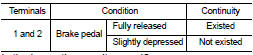
3. Check the continuity between stop lamp switch terminals under the following conditions.
Is the inspection result normal? YES >> INSPECTION END
NO >> GO TO 2.
2.CHECK STOP LAMP SWITCH-II
1. Adjust stop lamp switch installation. Refer to BR-22, "Inspection and Adjustment" (LHD models) or BR-90, "Inspection and Adjustment" (RHD models).Is the inspection result normal? YES >> INSPECTION END NO >> GO TO 2.
2.CHECK STOP LAMP SWITCH-II 1. Adjust stop lamp switch installation. Refer to BR-22, "Inspection and Adjustment" (LHD models) or BR-90, "Inspection and Adjustment" (RHD models).
2. Check the continuity between stop lamp switch terminals under the following conditions.
2. Check the continuity between stop lamp switch terminals under the following conditions.
Is the inspection result normal? YES >> INSPECTION END
NO >> Replace stop lamp switch.
 P1564 ASCD steering switch
DTC Logic
DTC DETECTION LOGIC
NOTE:
If DTC P1564 is displayed with DTC P0605, first perform the trouble diagnosis
for DTC P0605. Refer to
EC-683, "DTC Logic".
DTC CONFIRMATION PROCE ...
 P1574 ASCD vehicle speed sensor
Description
The ECM receives two vehicle speed sensor signals via CAN communication line.
One is sent from combination
meter, and the other is from TCM (Transmission control module). The ECM uses ...
Other materials:
P0037, P0038 HO2S2 heater
DTC Logic
DTC DETECTION LOGIC
DTC CONFIRMATION PROCEDURE
1.PRECONDITIONING
If DTC Confirmation Procedure has been previously conducted, always perform
the following procedure
before conducting the next test.
1. Turn ignition switch OFF and wait at least 10 seconds.
2. Turn ignition swit ...
Magnet clutch
Component Function Check
1.CHECK MAGNET CLUTCH OPERATION
Perform auto active test of IPDM E/R. Refer to PCS-12, "Diagnosis
Description" (with Intelligent Key) or PCS-
43, "Diagnosis Description" (without Intelligent Key).
Does it operate normally?
YES >> INSPECTION ...
Front fog lamp circuit
Component Function Check
1.CHECK FRONT FOG LAMP OPERATION
CONSULT-III ACTIVE TEST
1. Select ŌĆ£EXTERNAL LAMPSŌĆØ of IPDM E/R active test item.
2. With operating the test items, check that the front fog lamp is turned ON.
Fog : Front fog lamp ON
Off : Front fog lamp OFF
Is the measurement norm ...
