Nissan Juke Service and Repair Manual : P1564 ASCD steering switch
DTC Logic
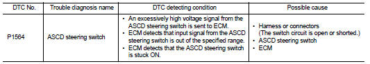
DTC DETECTION LOGIC
NOTE
:
If DTC P1564 is displayed with DTC P0605, first perform the trouble diagnosis
for DTC P0605. Refer to
EC-683, "DTC Logic".
DTC CONFIRMATION PROCEDURE
1.PRECONDITIONING
If DTC Confirmation Procedure has been previously conducted, always turn ignition switch OFF and wait at least 10 seconds before conducting the next test.
>> GO TO 2.
2.PERFORM DTC CONFIRMATION PROCEDURE
1. Turn ignition switch ON and wait at least 10 seconds.
2. Press CANCEL switch for at least 10 seconds, then release it and wait at least 10 seconds.
3. Press RESUME/ACCELERATE switch for at least 10 seconds, then release it and wait at least 10 seconds.
4. Press SET/COAST switch for at least 10 seconds, then release it and wait at least 10 seconds.
5. Check DTC.
Is DTC detected? YES >> Go to EC-714, "Diagnosis Procedure".
NO >> INSPECTION END
Diagnosis Procedure
1.CHECK GROUND CONNECTION
1. Turn ignition switch OFF.
2. Check ground connection E21 and E38. Refer to Ground Inspection in GI-44, "Circuit Inspection".
Is the inspection result normal? YES >> GO TO 2.
NO >> Repair or replace ground connection.
2.CHECK ASCD STEERING SWITCH CIRCUIT
 With CONSULT-III
1. Turn ignition switch ON.
2. Select “ENGINE” using CONSULT-III.
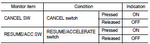
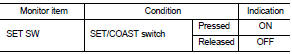
3. Select “CANCEL SW”, “RESUME/ACC SW” and “SET SW” in “DATA MONITOR” mode.
4. Check each item indication under the following conditions.
 Without CONSULT-III
1. Turn ignition switch ON.
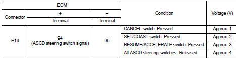
2. Check the voltage between ECM harness connector terminals under the following conditions.
Is the inspection result normal? YES >> GO TO 8.
NO >> GO TO 3.
3.CHECK ASCD STEERING SWITCH GROUND CIRCUIT FOR OPEN AND SHORT
1. Turn ignition switch OFF.
2. Disconnect ECM harness connector.
3. Disconnect combination switch harness connector.
4. Check the continuity between combination switch and ECM harness connector.
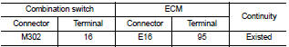
5. Also check harness for short to ground and short to power.
Is the inspection result normal? YES >> GO TO 5.
NO >> GO TO 4.
4.DETECT MALFUNCTIONING PART
Check the following.
• Combination switch (spiral cable) • Harness for open and short between ECM and combination switch >> Repair open circuit, short to ground or short to power in harness or connectors.
5.CHECK ASCD STEERING SWITCH INPUT SIGNAL CIRCUIT FOR OPEN AND SHORT
1. Check the continuity between combination switch and ECM harness connector.
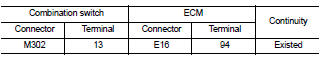
2. Also check harness for short to ground and short to power.
Is the inspection result normal? YES >> GO TO 7.
NO >> GO TO 6.
6.DETECT MALFUNCTIONING PART
Check the following.
• Combination switch (spiral cable) • Harness for open and short between ECM and combination switch
>> Repair open circuit, short to ground or short to power in harness or connectors.
7.CHECK ASCD STEERING SWITCH
Refer to EC-716, "Component Inspection (ASCD STEERING SWITCH)".
Is the inspection result normal? YES >> GO TO 8.
NO >> Replace ASCD steering switch.
8.CHECK INTERMITTENT INCIDENT
Refer to GI-42, "Intermittent Incident".
>> INSPECTION END
Component Inspection (ASCD STEERING SWITCH)
1.CHECK ASCD STEERING SWITCH-I
1. Turn ignition switch OFF.
2. Disconnect combination switch (spiral cable) harness connector.
3. Check the continuity between combination switch harness connector terminals under the following condition.
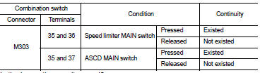
Is the inspection result normal? YES >> GO TO 2.
NO >> Replace ASCD steering switch.
2.CHECK ASCD STEERING SWITCH-II
Check resistance between combination switch (spiral cable) harness connector terminals under the following conditions.
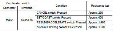
Is the inspection result normal? YES >> INSPECTION END
NO >> Replace ASCD steering switch.
 P1556, P1557 battery temperature sensor
DTC Logic
DTC DETECTION LOGIC
DTC CONFIRMATION PROCEDURE
1.PRECONDITIONING
1. Turn ignition switch OFF and wait at least 10 seconds.
2. Turn ignition switch ON.
3. Turn ignition switch OFF and ...
 P1572 ASCD brake switch
DTC Logic
DTC DETECTION LOGIC
NOTE:
• If DTC P1572 is displayed with DTC P0605, first perform the trouble diagnosis
for DTC P0605. Refer
to EC-683, "DTC Logic".
• This self-diagno ...
Other materials:
Removal and Installation
REMOVAL
1. Separate the rear propeller shaft. Refer to DLN-121, "Removal and
Installation".
2. Remove right side drive shaft. Refer to FAX-24, "RIGHT SIDE : Removal and
Installation".
3. Remove catalyst convertor support bracket (RH). EM-35, "4WD : Removal and
Insta ...
Diagnosis system (bcm) (without intelligent key system)
Common item
COMMON ITEM : CONSULT-III Function (BCM - COMMON ITEM)
APPLICATION ITEM
CONSULT-III performs the following functions via CAN communication with BCM.
SYSTEM APPLICATION
BCM can perform the following functions for each system.
NOTE:
It can perform the diagnosis modes except the ...
Intelligent Blind Spot Intervention (I-BSI)
WARNING
Failure to strictly adhere to these safety warnings and operational instructions for the Intelligent Blind Spot Intervention (I-BSI) system could result in unpredictable vehicle behavior, potentially leading to serious personal injury or fatal accidents.
The I-BSI system ...
