Nissan Juke Service and Repair Manual : Speed limiter main switch
Component Function Check
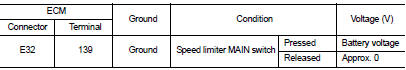
1.CHECK SPEED LIMITER MAIN SWITCH FUNCTION
1. Turn ignition switch ON.
2. Check the voltage between ECM harness connector terminals under the following conditions
Is the inspection result normal? YES >> INSPECTION END
NO >> Go to EC-1020, "Diagnosis Procedure".
Diagnosis Procedure
1.CHECK GROUND CONNECTION
1. Turn ignition switch OFF.
2. Check ground connection E38. Refer to Ground Inspection in GI-44, "Circuit Inspection".
Is the inspection result normal? YES >> GO TO 2.
NO >> Repair or replace ground connection.
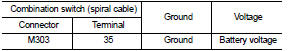
2.CHECK SPEED LIMITER MAIN SWITCH POWER SUPPLY CIRCUIT
1. Turn ignition switch OFF.
2. Disconnect combination switch (spiral cable) harness connector.
3. Turn ignition switch ON.
4. Check voltage between combination switch (spiral cable) harness connector and ground.
Is the inspection result normal? YES >> GO TO 4.
NO >> GO TO 3.
3.DETECT MALFUNCTIONING PART
Check the following.
• Combination switch (spiral cable)
• 10 A fuse (No. 2)
• Harness for open and short between combination switch (spiral cable) and
ground.
>> Repair open circuit, short to ground or short to power in harness or connectors.
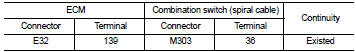
4.CHECK SPEED LIMITER MAIN SWITCH INPUT SIGNAL CIRCUIT FOR OPEN AND SHORT
1. Turn ignition switch OFF.
2. Disconnect ECM harness connector.
3. Check the continuity between ECM harness connector and combination switch (spiral cable) harness connector.
4. Also check harness for short to ground and short to power.
Is the inspection result normal? YES >> GO TO 6.
NO >> GO TO 5.
5.DETECT MALFUNCTIONING PART
Check the following.
• Harness connector E105, M77 • Combination switch (spiral cable) • Harness for open and short between ECM and combination switch (spiral cable)
>> Repair open circuit, short to ground or short to power in harness or connectors.
6.CHECK ASCD STEERING SWITCH
Refer to EC-1021, "Component Inspection".
Is the inspection result normal? YES >> GO TO 7.
NO >> Replace ASCD steering switch.
7.CHECK INTERMITTENT INCIDENT
Refer to GI-42, "Intermittent Incident", ???INCIDENT SIMULATION TESTS??? and ???GROUND INSPECTION???.
>> INSPECTION END
Component Inspection
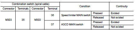
1.CHECK ASCD STEERING SWITCH-I
1. Turn ignition switch OFF.
2. Disconnect combination switch (spiral cable) harness connector.
3. Check the continuity between combination switch (spiral cable) harness connector terminals under the following condition.
Is the inspection result normal? YES >> GO TO 2.
NO >> Replace ASCD steering switch.
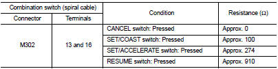
2.CHECK ASCD STEERING SWITCH-II
Check resistance between combination switch (spiral cable) harness connector terminals under the following conditions.
Is the inspection result normal? YES >> INSPECTION END
NO >> Replace ASCD steering switch.
 Malfunction indicator
Component Function Check
1.CHECK MI FUNCTION
1. Turn ignition switch ON.
2. Make sure that MI lights up.
Is the inspection result normal?
YES >> INSPECTION END
NO >> Go to EC-1019, ...

Other materials:
Brake pedal
Inspection and Adjustment
INSPECTION
Brake Pedal Height
Check the height (H1) between the dash lower panel (1) and the
brake pedal upper surface.
H1 : Refer to BR-136, "Brake Pedal".
CAUTION:
Remove the floor trim.
Stop Lamp Switch
Check the clearance (C) among the brake pedal l ...
Diagnosis system (BCM) (with intelligent key system)
Description
Air conditioning system performs self-diagnosis, operation check, function
diagnosis, and various settings
using diagnosis function of each control unit.
Common item : consult-III Function (BCM - COMMON ITEM)
APPLICATION ITEM
CONSULT-III performs the following functions via CAN ...
ACC warning does not operate
Diagnosis Procedure
1.CHECK COMBINATION METER BUZZER
Check combination meter buzzer.
Refer to WCS-40, "Component Function Check".
Is the inspection result normal?
YES >> GO TO 2.
NO >> Repair or replace the malfunctioning parts.
2.REPLACE BCM
1. Replace BCM. Ref ...
