Nissan Juke Service and Repair Manual : Basic inspection
DIAGNOSIS AND REPAIR WORK FLOW
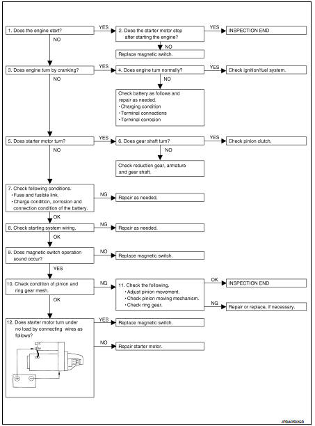
Work Flow
OVERALL SEQUENCE
DETAILED FLOW
NOTE
:
If any malfunction is found, immediately disconnect the battery cable from the
negative terminal.
1.CHECK ENGINE START
Crank the engine and check that the engine starts.
Does the engine start? YES >> GO TO 2.
NO >> GO TO 3.
2.CHECK THAT THE STARTER MOTOR STOPS
Check that the starter motor stops after starting the engine.
Does the starter motor stop? YES >> INSPECTION END
NO >> Replace magnetic switch.
3.CHECK THE ENGINE SPEED WITH CRANKING
Check that the engine runs at cranking.
Does engine turn by cranking? YES >> GO TO 4.
NO >> GO TO 5.
4.CHECK THE ENGINE SPEED WITH CRANKING
Check that the engine speed is not low at cranking.
Does engine turn normally? YES >> Check ignition/fuel system.
NO >> Check charge condition, corrosion and connection condition of the battery. Refer to PG-113, "Work Flow".
5.CHECK STARTER MOTOR ACTIVATION
Check that the starter motor runs at cranking.
Does starter motor turn? YES >> GO TO 6.
NO >> GO TO 7.
6.CHECK STARTER MOTOR UNIT
1. Remove starter motor.
2. Check that the gear shaft of starter motor rotates.
Does gear shaft turn? YES >> Check pinion clutch. Refer to STR-24, "HR16DE : Inspection and Adjustment" (HR16DE) or STR- 30, "MR16DDT : Inspection and Adjustment" (MR16DDT).
NO >> Check reduction gear, armature and gear shaft.
7.CHECK POWER SUPPLY CIRCUIT
Check the following conditions.
• Fuse and fusible link
• Charge condition, corrosion and connection condition of the battery. Refer to PG-113, "Work Flow".
Are these inspection results normal? YES >> GO TO 8.
NO >> Repair as needed.
8.CHECK STARTING SYSTEM WIRING
Check the following.
• “B” terminal circuit. Refer to STR-17, "Diagnosis Procedure".
• “S” terminal circuit. Refer to STR-19, "Diagnosis Procedure".
Are these inspection results normal? YES >> GO TO 9.
NO >> Repair as needed.
9.CHECK MAGNETIC SWITCH OPERATION SOUND
Check that a magnetic switch operation sound can be heard when the ignition switch is set at the starting position.
Does magnetic switch operation sound occur? YES >> GO TO 10.
NO >> Replace magnetic switch.
10.PINION AND RING GEAR ENGAGEMENT CHECK
Check condition of pinion and ring gear mesh.
Is the inspection result normal? YES >> GO TO 12.
NO >> GO TO 11.
11.CHECK STARTER MOTOR UNIT
Check the following.
• Adjust pinion movement. Refer to STR-24, "HR16DE : Inspection and Adjustment" (HR16DE) or STR-30, "MR16DDT : Inspection and Adjustment" (MR16DDT).
• Check pinion moving mechanism.
• Check ring gear.
Are these inspection results normal? YES >> INSPECTION END
NO >> Repair or replace, if necessary.
12.CHECK STARTER MOTOR UNIT
Check that the starter motor runs when connecting the positive terminal (12 V) to starter motor terminal M and the negative terminal (ground) to starter motor body.
Does the starter motor run? YES >> Replace magnetic switch.
NO >> Repair starter motor.
 Starting system (without intelligent key)
CVT : Wiring Diagram
For connector terminal arrangements, harness layouts, and alphabets in a
(option abbreviation; if not
described in wiring diagram), refer to GI-12, "Connector Information/ ...

Other materials:
Power supply and ground circuit
Diagnosis Procedure
1.CHECK FUSE
Is the fuse fusing?
YES >> Replace the fuse after repairing the applicable circuit.
NO >> GO TO 2.
2.CHECK GROUND CONNECTION
1. Turn ignition switch OFF.
2. Check ground connection E21 and E38. Refer to GI-44, "Circuit Inspection".
...
DPF (diesel particulate filter) data clear
Description
Perform ???DIESEL PARTICULATE FILTER DATA CLEAR??? in ???WORK SUPPORT??? mode with
CONSULT-III
when oxidation catalyst with diesel particulate filter is replaced as new one.
Based on the signal from sensors
ECM estimates the amount of particulate matter in diesel particulate filte ...
P17B4 low brake solenoid
DTC Logic
DTC DETECTION LOGIC
DTC CONFIRMATION PROCEDURE
1.PREPARATION BEFORE WORK
If another "DTC CONFIRMATION PROCEDURE" occurs just before, turn ignition
switch OFF and wait for at
least 10 seconds, then perform the next test.
>> GO TO 2.
2.CHECK DTC DETECTION
1. S ...
