Nissan Juke Service and Repair Manual : Starting system (without intelligent key)
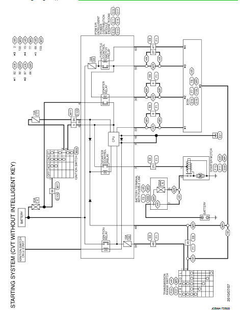
CVT : Wiring Diagram
For connector terminal arrangements, harness layouts, and alphabets in a
 (option abbreviation; if not
described in wiring diagram), refer to GI-12, "Connector Information/Explanation
of Option Abbreviation".
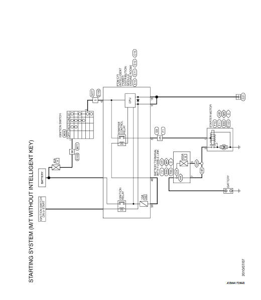
M/T : Wiring Diagram
For connector terminal arrangements, harness layouts, and alphabets in a
 (option abbreviation; if not
described in wiring diagram), refer to GI-12, "Connector Information/Explanation
of Option Abbreviation".
 Starting system (with intelligent key)
CVT : Wiring Diagram
For connector terminal arrangements, harness layouts, and alphabets in a
(option abbreviation; if not
described in wiring diagram), refer to GI-12, "Connector Information/ ...
 Basic inspection
DIAGNOSIS AND REPAIR WORK FLOW
Work Flow
OVERALL SEQUENCE
DETAILED FLOW
NOTE:
If any malfunction is found, immediately disconnect the battery cable from the
negative terminal.
1.CHECK ENGI ...
Other materials:
Recommended fluids and lubricants
Fluids and Lubricants
*1: For additional information, see ŌĆ£SAE Viscosity NumberŌĆØ.
*2: Use Genuine NISSAN Engine Coolant or equivalent in its quality, in order to
avoid possible aluminium corrosion within the engine
cooling system caused by the use of non-genuine engine coolant. Note that ...
Door lock operation warning does not operate
Diagnosis Procedure
1.CHECK DOOR LOCK FUNCTION
Check door lock function.
Does door lock/unlock using door request switch?
YES >> GO TO 2.
NO >> Refer to DLK-256, "Component Function Check".
2.CHECK INTELLIGENT KEY WARNING BUZZER
Check Intelligent Key warning buzzer ...
P0713 transmission fluid temperature sensor A
DTC Logic
DTC CONFIRMATION PROCEDURE
1.PREPARATION BEFORE WORK
If another "DTC CONFIRMATION PROCEDURE" occurs just before, turn ignition
switch OFF and wait for at
least 10 seconds, then perform the next test.
>> GO TO 2.
2.PERFORM DTC CONFIRMATION PROCEDURE
1. Start the ...
