Nissan Juke Service and Repair Manual : Back door lock
Exploded View
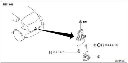
1. Back door lock assembly
2. TORX bolt
3. Back door striker
 : Do not reuse
 : N·m (kg-m, ft-lb)
 : Body grease
Door lock
DOOR LOCK : Removal and Installation
REMOVAL
1. Remove the back door lower finisher. Refer to INT-35, "BACK DOOR LOWER FINISHER : Removal and Installation".
2. Remove back door lock assembly mounting bolts.
3. Disconnect back door lock connector, and then remove back door lock assembly.
INSTALLATION
Note the following item, and install in the reverse order of removal.
CAUTION:
After installation, check back door open/close, and lock/unlock operation.
Emergency lever
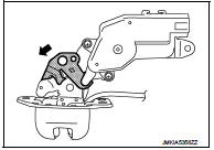
EMERGENCY LEVER : Unlock procedures
UNLOCK PROCEDURES
NOTE
:
If back door lock cannot be unlocked due to a malfunction or battery discharge,
follow the procedures to
unlock back door.
1. Remove emergency lid. Refer to INT-36, "EMERGENCY LID : Removal and Installation".
2. From inside the vehicle, rotate emergency lever toward lower direction and unlock.
 Rear door lock
Exploded View
1. Outside handle assembly
2. Rear door sealing screen
3. Door lock assembly
4. TORX bolt
5. Inside handle
: Clip
: Pawl
: Vehicle front
: Do not reuse
: N·m (kg-m, in-lb ...
 Fuel filler lid opener
Exploded View
1. Fuel filler lid opener cable
2. Cable protector
3. Fuel filler lid lock assembly
4. Fuel filler lid assembly
5. Spring
6. Bumper rubber
: Clip
: Do not reuse
Fuel fille ...
Other materials:
Meters and gauges
1. Tachometer
2. Engine coolant temperature gauge
3. Vehicle information display
— Odometer/twin trip odometer
— Trip computer
— Torque vectoring AWD (AWD model)
— Outside air temperature
4. Fuel gauge
5. Speedometer
6. Warning/indicator lights
7. Instrument brightness control kn ...
12-volt battery saver system
To preserve the operational integrity of your electric vehicle, an automated 12-volt battery saver system is integrated into the vehicle's power management logic. When all the following specific operating conditions are simultaneously met and sustained for a predetermined perio ...
Door request switch
Component Function Check
1.CHECK FUNCTION
1. Select “INTELLIGENT KEY” of “BCM” using CONSULT-III.
2. Select “REQ SW-DR”, “REQ SW-AS” in “DATA MONITOR” mode.
3. Check that the function operates normally according to the following
conditions.
Is the inspection result norma ...
