Nissan Juke Service and Repair Manual : Door request switch
Component Function Check
1.CHECK FUNCTION
1. Select “INTELLIGENT KEY” of “BCM” using CONSULT-III.
2. Select “REQ SW-DR”, “REQ SW-AS” in “DATA MONITOR” mode.
3. Check that the function operates normally according to the following conditions.
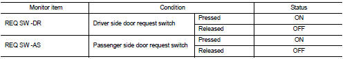
Is the inspection result normal? YES >> Front door request switch is OK.
NO >> Refer to DLK-256, "Diagnosis Procedure".
Diagnosis Procedure
1.CHECK DOOR REQUEST SWITCH INPUT SIGNAL
1. Turn ignition switch OFF.
2. Disconnect malfunctioning front door request switch connector.
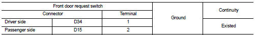
3. Check voltage between malfunctioning front door request switch harness connector and ground.
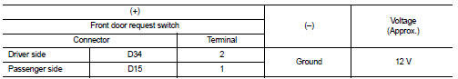
Is the inspection result normal? YES >> GO TO 3.
NO >> GO TO 2.
2.CHECK DOOR REQUEST SWITCH CIRCUIT
1. Disconnect BCM connector.
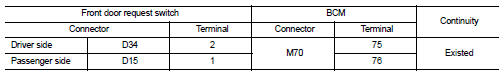
2. Check continuity between malfunctioning front door request switch harness connector and BCM harness connector.
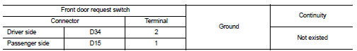
3. Check continuity between malfunctioning front door request switch harness connector and ground.
Is the inspection result normal? YES >> Replace BCM. Refer to BCS-93, "Removal and Installation".
NO >> Repair or replace harness.
3.CHECK DOOR REQUEST SWITCH GROUND CIRCUIT
Check continuity between malfunctioning front door request switch harness connector and ground.
Is the inspection result normal? YES >> GO TO 4.
NO >> Repair or replace harness.
4.CHECK DOOR REQUEST SWITCH
Refer to DLK-257, "Component Inspection".
Is the inspection result normal? YES >> GO TO 5.
NO >> Replace malfunctioning front door request switch.
5.CHECK INTERMITTENT INCIDENT
Refer to GI-42, "Intermittent Incident".
>> INSPECTION END
Component Inspection
1.CHECK DOOR REQUEST SWITCH
1. Turn ignition switch OFF.
2. Disconnect malfunctioning front door request switch connector.
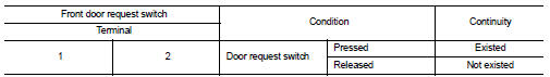
3. Check continuity between malfunctioning front door request switch terminals.
Is the inspection result normal? YES >> INSPECTION END
NO >> Replace malfunctioning front door request switch.
 Door lock and unlock switch
Component Function Check
1.CHECK FUNCTION
1. Select “DOOR LOCK” of “BCM” using CONSULT-III.
2. Select “CDL LOCK SW”, “CDL UNLOCK SW” in “DATA MONITOR” mode.
3. Check that the f ...
 Door switch
Component Function Check
1.CHECK FUNCTION
1. Select “DOOR LOCK” of “BCM” using CONSULT-III.
2. Select “DOOR SW-DR”, “DOOR SW-AS”, “DOOR SW-RL”, “DOOR SW-RR”, “DOOR SW-BK†...
Other materials:
4WD mode indicator lamp (4WD-V)
Component Function Check
1.4WD MODE INDICATOR LAMP OPERATION CHECK
1. Turn the ignition switch ON.
2. Change 4WD mode switch to “4WD-V”.
3. Check that 4WD mode indicator lamp (4WD-V) turns on.
Is the inspection result normal?
YES >> INSPECTION END
NO >> Proceed to diagnosis ...
System description
VENTILATION SYSTEM
System Description
OUTLINE
Ventilation system is controlled by A/C auto amp. (AUTOMATIC AIR
CONDITIONING) or A/C control (MANUAL
AIR CONDITIONING and MANUAL HEATER). For details of air conditioner system,
refer to HAC-17,
"System Description" (AUTOMATIC AIR COND ...
Precaution Necessary for Steering Wheel Rotation after Battery Disconnect
NOTE:
• Before removing and installing any control units, first turn the ignition
switch to the LOCK position, then disconnect
both battery cables.
• After finishing work, confirm that all control unit connectors are connected
properly, then re-connect both
battery cables.
• Always us ...
