Nissan Juke Service and Repair Manual : Door cable
Exploded View
LEFT SIDE
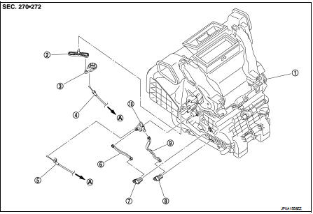
1. A/C unit assembly
2. Intake door lever
3. Intake door link
4. Intake door cable
5. Air mix door cable
6. Upper air mix door rod
7. Upper air mix door lever
8. Lower air mix door lever
9. Lower air mix door rod
10. Air mix door link
A. To A/C control
RIGHT SIDE
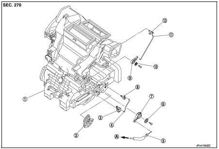
1. A/C unit assembly
2. Main link
3. Sub defroster door link
4. Sub defroster door rod
5. Mode door cable
6. Plate
7. Mode link
8. Sub defroster door lever
9. Center ventilator and defroster door link
10. Plate
11. Center ventilator and defroster door rod
12. Center ventilator and defroster door lever
A. To A/C control
Intake door cable : Removal and Install
REMOVAL
1. Disconnect intake door cable from A/C control. Refer to HAC-239, "Exploded View".
2. Remove instrument lower panel LH. Refer to IP-13, "Removal and Installation".
(LHD models)
3. Remove glove box assembly. Refer to IP-13, "Removal and Installation". (RHD
models)
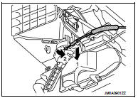
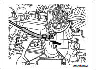
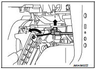
4. Disconnect intake door cable from A/C unit assembly as shown
by the arrow in the figure, and then remove intake door cable.
INSTALLATION
Install in the reverse order of removal.
Mode door cable : Removal and Installation
REMOVAL
1. Disconnect mode door cable from A/C control. Refer to HAC-239, "Exploded View".
2. Remove glove box assembly. Refer to IP-13, "Removal and Installation". (LHD
models)
3. Remove instrument panel RH. Refer to IP-13, "Removal and Installation". (RHD
models)
4. Disconnect mode door cable from A/C unit assembly as shown
by the arrow in the figure, and then remove mode door cable.
INSTALLATION
Install in the reverse order of removal.
Air mix door cable : Removal and Installation
REMOVAL
1. Disconnect air mix door cable from A/C control. Refer to HAC-239, "Exploded View".
2. Remove instrument panel LH. Refer to IP-13, "Removal and Installation". (LHD
models)
3. Remove glove box assembly. Refer to IP-13, "Removal and Installation". (RHD
models)
4. Disconnect air mix door cable from A/C unit assembly as shown
by the arrow in the figure, and then remove air mix door cable.
INSTALLATION
Install in the reverse order of removal.
 Blower fan resistor
Exploded View
1. A/C unit assembly
2. Blower fan resistor*1
3. Sub harness*1
4. Power transistor*2
5. Sub harness*2
6. Blower motor
• *1: Manual air conditioner
• *2: Automatic air c ...

Other materials:
B2618 BCM
DTC Logic
DTC DETECTION LOGIC
NOTE:
• If DTC B2618 is displayed with DTC U1000, first perform the trouble diagnosis
for DTC U1000. Refer to
BCS-83, "DTC Logic".
• If DTC B2618 is displayed with DTC U1010, first perform the trouble diagnosis
for DTC U1010. Refer to
BCS-84, &qu ...
P0605 ECM
DTC Logic
DTC DETECTION LOGIC
DTC CONFIRMATION PROCEDURE
1.PRECONDITIONING
If DTC Confirmation Procedure has been previously conducted, always turn
ignition switch OFF and wait at
least 10 seconds before conducting the next test.
>> GO TO 2.
2.PERFORM DTC CONFIRMATION PROCEDURE ...
Front door lock
Exploded View
1. Door key cylinder assembly (driver
side)
Outside handle escutcheon (passenger
side)
2. Outside handle
3. Front gasket
4. Inside handle
5. TORX bolt
6. Door lock assembly
7. Key rod (driver side)
8. Outside handle bracket
9. Rear gasket
10. Key rod protector (driv ...
