Nissan Juke Service and Repair Manual : Door lock and unlock switch
Component Function Check
1.CHECK FUNCTION
1. Select ÔÇťDOOR LOCKÔÇŁ of ÔÇťBCMÔÇŁ using CONSULT-III.
2. Select ÔÇťCDL LOCK SWÔÇŁ, ÔÇťCDL UNLOCK SWÔÇŁ in ÔÇťDATA MONITORÔÇŁ mode.
3. Check that the function operates normally according to the following conditions.
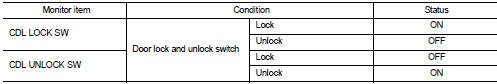
Is the inspection result normal? YES >> Door lock and unlock switch is OK.
NO >> Refer to DLK-254, "Diagnosis Procedure".
Diagnosis Procedure
1.CHECK DOOR LOCK AND UNLOCK SWITCH INPUT SIGNAL
1. Turn ignition switch OFF.
2. Disconnect power window main switch connector.
3. Check signal between power window main switch harness connector and ground using oscilloscope.
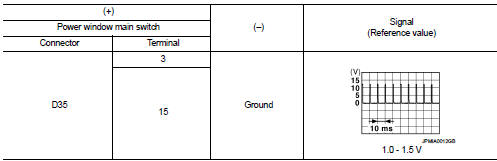
Is the inspection result normal? YES >> GO TO 3.
NO >> GO TO 2.
2.CHECK DOOR LOCK AND UNLOCK SWITCH CIRCUIT
1. Disconnect BCM connector and front power window switch (passenger side) connector.
2. Check continuity between BCM harness connector and power window main switch harness connector.
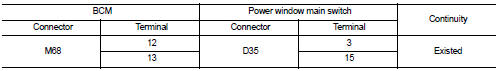
3. Check continuity between BCM harness connector and ground.
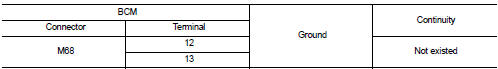
Is the inspection result normal? YES >> Replace BCM. Refer to BCS-93, "Removal and Installation".
NO >> Repair or replace harness.
3.CHECK DOOR LOCK AND UNLOCK SWITCH GROUND
Check continuity between power window main switch harness connector and ground.
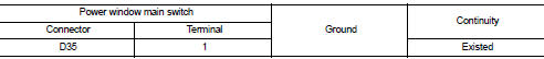
Is the inspection result normal? YES >> GO TO 4.
NO >> Repair or replace harness.
4.CHECK DOOR LOCK AND UNLOCK SWITCH
Refer to DLK-255, "Component Inspection".
Is the inspection result normal? YES >> GO TO 5.
NO >> Replace power window main switch. Refer to PWC-44, "Removal and Installation".
5.CHECK INTERMITTENT INCIDENT
Refer to GI-42, "Intermittent Incident".
>> INSPECTION END
Component Inspection
1.CHECK DOOR LOCK AND UNLOCK SWITCH
1. Turn ignition switch OFF.
2. Disconnect power window main switch connector.
3. Check continuity between power window main switch terminals.
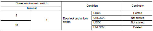
Is the inspection result normal? YES >> INSPECTION END
NO >> Replace power window main switch.
 Door lock actuator
Driver side
DRIVER SIDE : Component Function Check
1.CHECK FUNCTION
1. Select ÔÇťDOOR LOCKÔÇŁ of ÔÇťBCMÔÇŁ using CONSULT-III.
2. Select ÔÇťDOOR LOCKÔÇŁ in ÔÇťACTIVE TESTÔÇŁ mode.
3. Check that th ...
 Door request switch
Component Function Check
1.CHECK FUNCTION
1. Select ÔÇťINTELLIGENT KEYÔÇŁ of ÔÇťBCMÔÇŁ using CONSULT-III.
2. Select ÔÇťREQ SW-DRÔÇŁ, ÔÇťREQ SW-ASÔÇŁ in ÔÇťDATA MONITORÔÇŁ mode.
3. Check that the f ...
Other materials:
Continuously Variable Transmission (CVT)
The ignition lock is designed so that the ignition switch cannot be turned to
the LOCK position until the shift lever is moved to the P (Park) position.
ÔÇó When turning the ignition switch to the LOCK position, make sure that the shift
lever is in the P (Park) position.
ÔÇó When removing th ...
Forward-facing child restraint installation using the seat belts
WARNING
You must utilize the three-point seat belt system equipped with an Automatic Locking Retractor (ALR) whenever you install a child restraint in your Nissan Leaf.
Failure to properly engage the ALR mode prevents the child restraint from being secured correctly. A loose or unstable re ...
Push starting
Do not attempt to start the engine by pushing.
CAUTION
ÔÇó Continuously Variable Transmission (CVT) models cannot be pushstarted or
tow-started. Attempting to do so may cause transmission damage.
ÔÇó Three-way catalyst equipped models should not be started by pushing since the
three way catal ...
