Nissan Juke Service and Repair Manual : Evap canister
2WD : Hydraulic Layout
EVAPORATIVE EMISSION LINE DRAWING
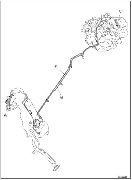
1.EVAP canister purge volume control
solenoid valve
2. EVAP canister
3. EAVP line
4. Fuel line
NOTE
:
Do not use soapy water or any type of solvent while installing vacuum hose or
purge hoses.
2WD : Removal and Installation
REMOVAL
1. Disconnect EVAP canister hoses.
2. Remove EVAP canister fixing bolt.
3. Remove EVAP canister.
INSTALLATION
Install in the reverse order of removal.
NOTE
:
Tighten EVAP canister fixing bolt to the specified torque.
4WD : Hydraulic Layout
EVAPORATIVE EMISSION LINE DRAWING
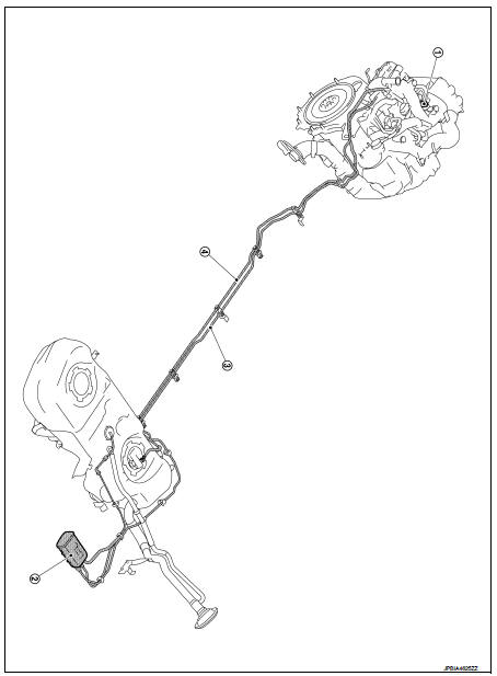
1. EVAP service port
2. EVAP canister
3. EVAP line
4. Fuel line
NOTE
:
Do not use soapy water or any type of solvent while installing vacuum hose or
purge hoses.
4WD : Removal and Installation
REMOVAL
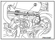
1. Remove rear stabilizer (1). Refer to RSU-34, "Exploded View".
2. Disconnect EVAP canister hoses.
3. Remove EVAP canister fixing bolt.
4. Remove EVAP canister (2).
INSTALLATION
Install in the reverse order of removal.
NOTE
:
Tighten EVAP canister fixing bolt to the specified torque.
 Fuel tank
2WD : Exploded View
1. Fuel filler cap
2. Grommet
3. Fuel filler tube
4. EVAP canister hose
5. Fuel tank mounting band (RH)
6. Fuel tank mounting band (LH)
7. Fuel tank
8. Clamp
9. Fu ...
 Service data and specifications (SDS)
Fuel Tank
Standard and Limit
...
Other materials:
Combination meter
Reference Value
VALUES ON THE DIAGNOSIS TOOL
NOTE:
Some items are not available according to vehicle specification.
TERMINAL LAYOU
PHYSICAL VALUES
Fail-Safe
FAIL-SAFE
The combination meter activates the fail-safe control if CAN communication
with each unit is malfunctio ...
Shift position indicator circuit
Component Parts Function Inspection
1.CHECK SHIFT POSITION INDICATOR
1. Start the engine.
2. Shift selector lever.
3. Check that the selector lever position and the shift position indicator on
the combination meter are identical.
Is the inspection result normal?
YES >> INSPECTION END ...
Door cable
Exploded View
LEFT SIDE
1. Heater unit assembly
2. Intake door lever
3. Intake door link
4. Intake door cable
5. Air mix door cable
6. Air mix door link
7. Air mix door rod
8. Lower air mix door lever
9. Upper air mix door lever
10. Max. cool door
A. To A/C control
RIGHT SIDE
...
