Nissan Juke Service and Repair Manual : Door switch
Component Function Check
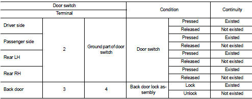
1.CHECK FUNCTION
1. Select “DOOR LOCK” of “BCM” using CONSULT-III.
2. Select “DOOR SW-DR”, “DOOR SW-AS”, “DOOR SW-RL”, “DOOR SW-RR”, “DOOR SW-BK” in “DATA MONITOR” mode.
3. Check that the function operates normally according to the following conditions.
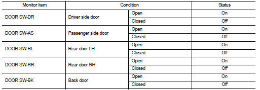
Is the inspection result normal? YES >> Door switch is OK.
NO >> Refer to DLK-258, "Diagnosis Procedure".
Diagnosis Procedure
1.CHECK DOOR SWITCH INPUT SIGNAL
1. Turn ignition switch OFF.
2. Disconnect malfunctioning door switch connector.
3. Check signal between malfunctioning door switch harness connector and ground using oscilloscope.
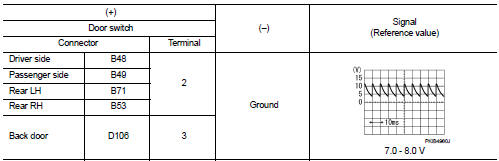
Is the inspection result normal? YES-1 >> Back door: GO TO 3.
YES-2 >> Other door: GO TO 4.
NO >> GO TO 2.
2.CHECK DOOR SWITCH CIRCUIT
1. Disconnect BCM connector.
2. Check continuity between door switch harness connector and BCM harness connector.
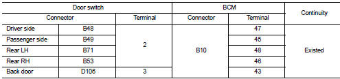
3. Check continuity between door switch harness connector and ground.
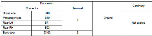
Is the inspection result normal? YES >> Replace BCM. Refer to BCS-93, "Removal and Installation".
NO >> Repair or replace harness.
3.CHECK BACK DOOR SWITCH CIRCUIT
Check continuity between back door lock assembly harness connector and ground.
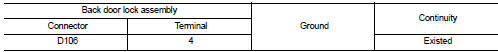
Is the inspection result normal? YES >> GO TO 4.
NO >> Repair or replace harness.
4.CHECK DOOR SWITCH
Refer to DLK-259, "Component Inspection".
Is the inspection result normal? YES >> GO TO 5.
NO >> Replace malfunctioning door switch.
5.CHECK INTERMITTENT INCIDENT
Refer to GI-42, "Intermittent Incident".
>> INSPECTION END
Component Inspection
1.CHECK DOOR SWITCH
1. Turn ignition switch OFF.
2. Disconnect malfunctioning door switch connector.
3. Check continuity between door switch terminals.
Is the inspection result normal? YES >> INSPECTION END
NO >> Replace malfunction door switch.
 Door request switch
Component Function Check
1.CHECK FUNCTION
1. Select “INTELLIGENT KEY” of “BCM” using CONSULT-III.
2. Select “REQ SW-DR”, “REQ SW-AS” in “DATA MONITOR” mode.
3. Check that the f ...
 Hazard function
Component Function Check
1.CHECK FUNCTION
1. Select “INTELLIGENT KEY” of “BCM” using CONSULT-III.
2. Select “FLASHER” in “ACTIVE TEST” mode.
3. Check that the function operates nor ...
Other materials:
Install
1. Align the head restraint/headrest stalks with the holes in the seat. Make
sure that the head restraint/headrest is facing the correct direction. The stalk
with the adjustment notch1 must be installed in the hole with the lock knob2 .
2. Push and hold the lock knob and push the head restrai ...
Removal and installation
HORN
Exploded View
WITHOUT VEHICLE SECURITY SYSTEM
1. Horn high
2. Horn low
3. Horn bracket
WITH VEHICLE SECURITY SYSTEM
1. Horn low
2. Horn bracket
Removal and Installation
REMOVAL
Without Vehicle Security System
1. Remove the front center grille and front side grille (LH/RH). Re ...
Vehicle does not enter 4WD mode
Description
Vehicle does not enter 4-wheel drive mode even though 4WD warning lamp turned
to OFF.
Diagnosis Procedure
1.CHECK 4WD WARNING LAMP
Turn the ignition switch ON.
Does 4WD warning lamp turn ON?
YES >> GO TO 2.
NO >> Proceed to diagnosis procedure. Refer to DLN-80, & ...
