Nissan Juke Service and Repair Manual : Push-button ignition switch position indicator
Description
Push-button ignition switch changes the power supply position.
BCM maintains the power supply position status.
BCM changes the power supply position with the operation of the push-button ignition switch.
Component Function Check
1.CHECK FUNCTION
Check push-button ignition switch (ŌĆ£PUSH SWITCH INDICATORŌĆØ) in Active Test Mode with CONSULT-III.
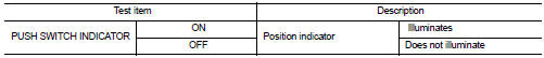
Is the inspection result normal? YES >> INSPECTION END
NO >> Refer to PCS-111, "Diagnosis Procedure".
Diagnosis Procedure
1.CHECK PUSH-BUTTON IGNITION SWITCH INPUT SIGNAL
1. Turn ignition switch OFF.
2. Disconnect push-button ignition switch connector.
3. Check voltage between push-button ignition switch harness connector and ground.
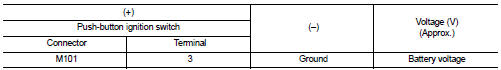
Is the inspection normal? YES >> GO TO 2.
NO-1 >> Check 10 A fuse [No.13, located in fuse block (J/B)].
NO-2 >> Check harness for open or short between push-button ignition switch and fuse.
2.CHECK BCM INPUT
1. Connect push-button ignition switch connector.
2. Disconnect BCM connector.
3. Check voltage between BCM connector and ground.
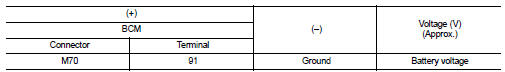
Is the inspection normal? YES >> Replace BCM. Refer to BCS-93, "Removal and Installation".
NO >> GO TO 3.
3.CHECK PUSH-BUTTON IGNITION SWITCH CIRCUIT
1. Disconnect push-button ignition switch connector.
2. Check continuity between BCM harness connector and push-button ignition switch harness connector.
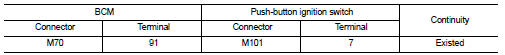
3. Check continuity between BCM harness connector and ground.
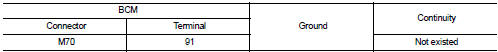
Is the inspection normal? YES >> Replace push-button ignition switch.
NO >> Repair or replace harness.
 Push-button ignition switch
Component Function Check
1.CHECK FUNCTION
1. Select ŌĆ£PUSH SWŌĆØ in ŌĆ£Data MonitorŌĆØ mode with CONSULT-III.
2. Check the push-button ignition switch signal under the following conditions.
Is ...

Other materials:
Front wheel hub and knuckle
Inspection
COMPONENT PART
Check that the mounting conditions (looseness, backlash) of each component
and component conditions
(wear, damage) are normal.
WHEEL HUB ASSEMBLY (BEARING-INTEGRATED TYPE)
Check the following items, and replace the part if necessary.
ŌĆó Move wheel hub assembly ...
Ignition position warning function does not operate
Diagnosis Procedure
1.CHECK DTC WITH BCM
Check that DTC is not detected with BCM.
Is the inspection result normal?
YES >> GO TO 2.
NO >> Refer to BCS-67, "DTC Index".
2.CHECK POWER DOOR LOCK OPERATION
Check power door lock operation.
Does door lock/unlock with d ...
Precaution Necessary for Steering Wheel Rotation after Battery Disconnect
NOTE:
ŌĆó Before removing and installing any control units, first turn the ignition
switch to the LOCK position, then disconnect
both battery cables.
ŌĆó After finishing work, confirm that all control unit connectors are connected
properly, then re-connect both
battery cables.
ŌĆó Always us ...
