Nissan Juke Service and Repair Manual : Push-button ignition switch
Component Function Check
1.CHECK FUNCTION
1. Select “PUSH SW” in “Data Monitor” mode with CONSULT-III.
2. Check the push-button ignition switch signal under the following conditions.
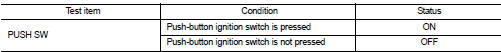
Is the indication normal? YES >> INSPECTION END.
NO >> Go to PCS-108, "Diagnosis Procedure".
Diagnosis Procedure
1.CHECK PUSH-BUTTON IGNITION SWITCH OUTPUT SIGNAL 1
1. Turn ignition switch OFF.
2. Disconnect push-button ignition switch connector and IPDM E/R connector.
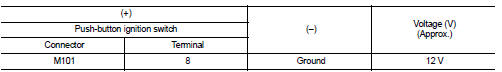
3. Check voltage between push-button ignition switch harness connector and ground.
Is the inspection result normal? YES >> GO TO 3.
NO >> GO TO 2.
2.CHECK PUSH-BUTTON IGNITION SWITCH CIRCUIT 1
1. Disconnect BCM connector.
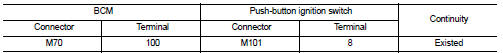
2. Check continuity between BCM harness connector and push-button ignition switch harness connector.
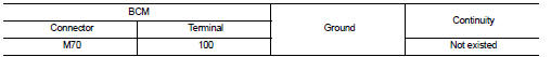
3. Check continuity between BCM harness connector and ground.
Is the inspection result normal? YES >> Replace BCM. Refer to BCS-93, "Removal and Installation".
NO >> Repair or replace harness.
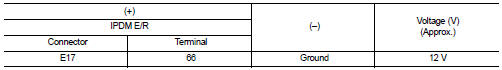
3.CHECK PUSH-BUTTON IGNITION SWITCH OUTPUT SIGNAL 2
Check voltage between IPDM E/R harness connector and ground.
Is the inspection result normal? YES >> GO TO 5.
NO >> GO TO 4.
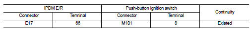
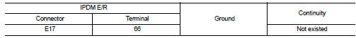
4.CHECK PUSH-BUTTON IGNITION SWITCH CIRCUIT 2
1. Disconnect BCM connector.
2. Check continuity between IPDM E/R harness connector and push-button ignition switch harness connector.
3. Check continuity between IPDM E/R harness connector and ground.
Is the inspection result normal? YES >> Replace IPDM E/R.
NO >> Repair or replace harness.
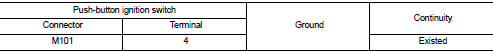
5.CHECK PUSH-BUTTON IGNITION SWITCH GROUND CIRCUIT
Check continuity between push-button ignition switch harness connector and ground
Is the inspection result normal? YES >> GO TO 6.
NO >> Repair or replace harness.
6.CHECK PUSH-BUTTON IGNITION SWITCH
Refer to PCS-109, "Component Inspection".
Is the inspection result normal? YES >> GO TO 7.
NO >> Replace push-button ignition switch.
7.CHECK INTERMITTENT INCIDENT
Refer to GI-42, "Intermittent Incident".
>> INSPECTION END
Component Inspection
1.CHECK PUSH-BUTTON IGNITION SWITCH
1. Turn ignition switch OFF.
2. Disconnect push-button ignition switch connector.
3. Check continuity between push-button ignition switch terminals.
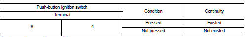
Is the inspection result normal? YES >> INSPECTION END
NO >> Replace push-button ignition switch.
 B26F6 BCM
DTC Logic
DTC DETECTION LOGIC
NOTE:
• If DTC B26F6 is displayed with DTC U1000, first perform the trouble diagnosis
for DTC U1000. Refer to
BCS-83, "DTC Logic".
• If DTC B26F6 is ...
 Push-button ignition switch position indicator
Description
Push-button ignition switch changes the power supply position.
BCM maintains the power supply position status.
BCM changes the power supply position with the operation of the push-b ...
Other materials:
CVT shift selector
Exploded View
1. Selector lever knob
2. Lock pin
3. Knob cover
4 Position indication panel
5. CVT shift selector assembly
6. CVT shift selector harness assembly
7. Detent switch*
8. Shift lock unit
9. Park position switch
:N·m (kg-m, it-lb)
*: With push engine starter
Removal an ...
RAB system operation
RAB warning light and dedicated system warning indicator
Steering-wheel-mounted control switches (located on the left side)
Center infotainment and information display
The RAB system is active whenever the shift lever is placed in the R (R ...
Fuel recommendation
NISSAN recommends the use of unleaded premium gasoline with an octane rating
of at least 91 AKI (Anti-Knock Index) number (Research octane number 96).
If unleaded premium gasoline is not available, you may use unleaded regular gasoline
with an octane rating of at least 87 AKI number (Research o ...
