Nissan Juke Service and Repair Manual : B26F6 BCM
DTC Logic
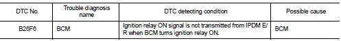
DTC DETECTION LOGIC
NOTE
:
ÔÇó If DTC B26F6 is displayed with DTC U1000, first perform the trouble diagnosis
for DTC U1000. Refer to
BCS-83, "DTC Logic".
ÔÇó If DTC B26F6 is displayed with DTC U1010, first perform the trouble diagnosis for DTC U1010. Refer to BCS-84, "DTC Logic".
DTC CONFIRMATION PROCEDURE
1.PERFORM DTC CONFIRMATION PROCEDURE
1. Turn ignition switch ON under the following conditions, and wait for 1 second or more.
CVT models
- Selector lever is in the P or N position
- Do not depress brake pedal
M/T models
- Do not depress clutch pedal
2. Check ÔÇťSelf-diagnosis resultÔÇŁ of BCM with CONSULT-III.
Is DTC detected? YES >> Go to PCS-107, "Diagnosis Procedure".
NO >> INSPECTION EN
Diagnosis Procedure
1.INSPECTION START
1. Turn ignition switch ON.
2. Select ÔÇťSelf-diagnosis resultÔÇŁ of BCM with CONSULT-III.
3. Touch ÔÇťERASEÔÇŁ.
4. Perform DTC Confirmation Procedure.
See PCS-107, "DTC Logic".
Is DTC detected? YES >> Replace BCM. Refer to BCS-93, "Removal and Installation" NO >> INSPECTION END
 B26F2 ignition relay
DTC Logic
DTC DETECTION LOGIC
DTC CONFIRMATION PROCEDURE
1.PERFORM DTC CONFIRMATION PROCEDURE
1. Turn ignition switch ON under the following conditions, and wait for 2
seconds or more.
CVT ...
 Push-button ignition switch
Component Function Check
1.CHECK FUNCTION
1. Select ÔÇťPUSH SWÔÇŁ in ÔÇťData MonitorÔÇŁ mode with CONSULT-III.
2. Check the push-button ignition switch signal under the following conditions.
Is ...
Other materials:
Intelligent Cruise Control (ICC) (for vehicles without ProPILOT Assist)
WARNING
Failure to follow these safety warnings and operational instructions regarding the Intelligent Cruise Control (ICC) system could lead to a loss of vehicle control, resulting in serious injury or death.
The ICC system is designed strictly as a driving ...
B terminal circuit
Description
The ÔÇťBÔÇŁ terminal is constantly supplied with battery power.
Diagnosis Procedure
CAUTION:
Perform diagnosis under the condition that engine cannot start by the following
procedure.
1. Remove fuel pump fuse.
2. Crank or start the engine (where possible) until the fuel pressur ...
P2118 throttle control motor
DTC Logic
DTC DETECTION LOGIC
DTC CONFIRMATION PROCEDURE
1.PRECONDITIONING
If DTC Confirmation Procedure has been previously conducted, always perform
the following procedure
before conducting the next test.
1. Turn ignition switch OFF and wait at least 10 seconds.
2. Turn ignition swit ...
