Nissan Juke Service and Repair Manual : B terminal circuit
Description
The ‚ÄúB‚ÄĚ terminal is constantly supplied with battery power.
Diagnosis Procedure
CAUTION:
Perform diagnosis under the condition that engine cannot start by the following
procedure.
1. Remove fuel pump fuse.
2. Crank or start the engine (where possible) until the fuel pressure is released.
1.INSPECTION START
Check which type of engine the vehicle is equipped with.
Which type of engine? HR16DE engine models>>GO TO 4.
Except HR16DE engine models>>GO TO 2.
2.CHECK FUSIBLE LINK
Check that the following fusible link is not blown.
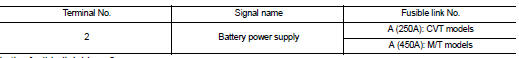
Is the fusible link blown? YES >> Replace the blown fusible link after repairing the affected circuit if a fusible link is blown.
NO >> GO TO 3.
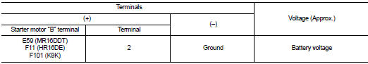
3.CHECK ‚ÄúB‚ÄĚ TERMINAL CIRCUIT
1. Turn ignition switch OFF.
2. Check that starter motor ‚ÄúB‚ÄĚ terminal connection is clean and tight.
3. Check voltage between starter motor ‚ÄúB‚ÄĚ terminal and ground.
Is the inspection result normal? YES >> GO TO 4.
NO >> Check harness between battery and starter motor for open circuit.
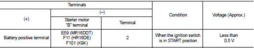
4.CHECK BATTERY CABLE CONNECTION STATUS (VOLTAGE DROP TEST)
1. Shift selector lever to ‚ÄúP‚ÄĚ or ‚ÄúN‚ÄĚ position. (CVT models) Keep depressing clutch pedal fully. (M/T models with Intelligent Key system) 2. Check voltage between battery positive terminal and starter motor ‚ÄúB‚ÄĚ terminal.
Is the inspection result normal? YES >> GO TO 5.
NO >> Check harness between the battery and the starter motor for poor continuity.
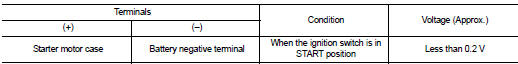
5.CHECK GROUND CIRCUIT STATUS (VOLTAGE DROP TEST)
1. Shift selector lever to ‚ÄúP‚ÄĚ or ‚ÄúN‚ÄĚ position. (CVT models) Keep depressing clutch pedal fully. (M/T models with Intelligent Key system) 2. Check voltage between starter motor case and battery negative terminal.
Is the inspection result normal? YES >> ‚ÄúB‚ÄĚ terminal circuit is OK. Further inspection is necessary. Refer to STR-14, "Work Flow".
NO >> Check the starter motor case and ground for poor continuity.

 S terminal circuit
Description
The starter motor magnetic switch is supplied with power when the ignition
switch is turned to the START position
while the selector lever is in the P or N position for CVT models or t ...
Other materials:
I-BSI system limitations
WARNING
The following points outline critical operational limitations for the Intelligent Blind Spot Intervention (I-BSI) system. Failing to operate your Nissan Leaf in strict accordance with these limitations could result in an inappropriate system response, potentially leading to serious inju ...
S terminal circuit
Description
The output voltage of the alternator is controlled by the IC voltage
regulator at the ‚ÄúS‚ÄĚ terminal detecting the
input voltage.
The ‚ÄúS‚ÄĚ terminal circuit detects the battery voltage to adjust the alternator
output voltage with the IC voltage
regulator.
Diagnosis Procedu ...
Basic inspection
DIAGNOSIS AND REPAIR WORKFLOW (METER SYSTEM)
Work flow
OVERALL SEQUENCE
‚ÄĘ Reference 1¬∑¬∑¬∑MWI-22, "On Board Diagnosis Function".
‚ÄĘ Reference 2¬∑¬∑¬∑MWI-36, "DTC Index".
‚ÄĘ Reference 3¬∑¬∑¬∑MWI-51, "COMBINATION METER : Diagnosis Procedure".
DETAILED FLOW
...
