
Nissan Juke Service and Repair Manual : Diagnosis system (IPDM E/R) (without intelligent key system)
Diagnosis Description
AUTO ACTIVE TEST
Description
In auto active test mode, the IPDM E/R sends a drive signal to the following
systems to check their operation.
• Oil pressure warning lamp (only for K9K engine models)
• Rear window defogger
• Front wiper motor
• Parking lamp
• License plate lamp
• Tail lamp
• Front fog lamp
• Headlamp (LO, HI)
• A/C compressor (magnet clutch)
• Cooling fan
Operation Procedure
CAUTION:
Wiper arm interferes with food when wiper is operated while wiper arm is in the
raised position.
Always perform auto active test without setting wiper arm in the raised position. Always pour water on front windshield glass in advance to auto active test so that damage on front windshield glass surface is prevented.
1. Turn the ignition switch OFF.
2. Turn the ignition switch ON, and within 20 seconds, press the driver door switch 10 times. Then turn the ignition switch OFF.
CAUTION:
Close passenger door.
3. Turn the ignition switch ON within 10 seconds. After that the horn sounds once and the auto active test starts.
CAUTION:
Engine starts when ignition switch is turned ON while brake pedal is depressed.
4. Oil pressure warning lamp starts blinking when the auto active test starts*. (only for K9K engine models)
*: Except for K9K engine models, oil pressure warning lamp turn ON when auto active test start.
5. After a series of the following operations is repeated 3 times, auto active test is completed.
NOTE
:
• When auto active test mode has to be cancelled halfway through test, turn the
ignition switch OFF.
• When auto active test is not activated, door switch may be the cause. Check door switch. Refer to DLK-397, "Component Function Check" (with super lock) or DLK-522, "Component Function Check" (without super lock).
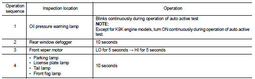
Inspection in Auto Active Test Mode When auto active test mode is actuated, the following operation sequence is repeated 3 times.

Concept of auto active test
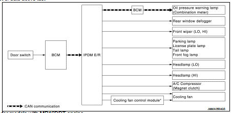
*: Only for models with MR16DDT engine
• IPDM E/R starts the auto active test with the door switch signals transmitted by BCM via CAN communication.
Therefore, the CAN communication line between IPDM E/R and BCM is considered normal if the auto active test starts successfully.
• The auto active test facilitates troubleshooting if any systems controlled by IPDM E/R cannot be operated.
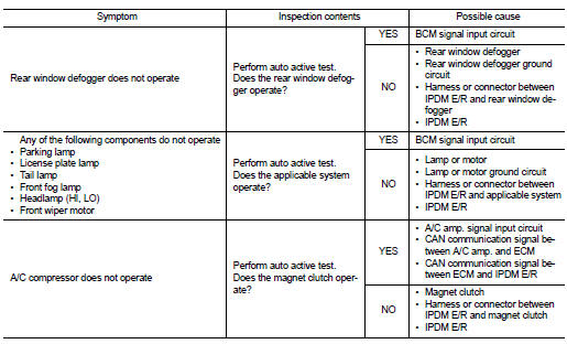
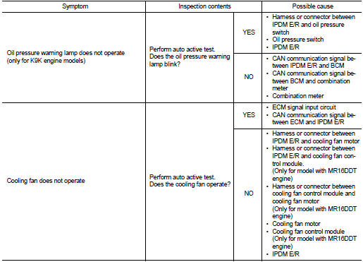
Diagnosis chart in auto active test mode
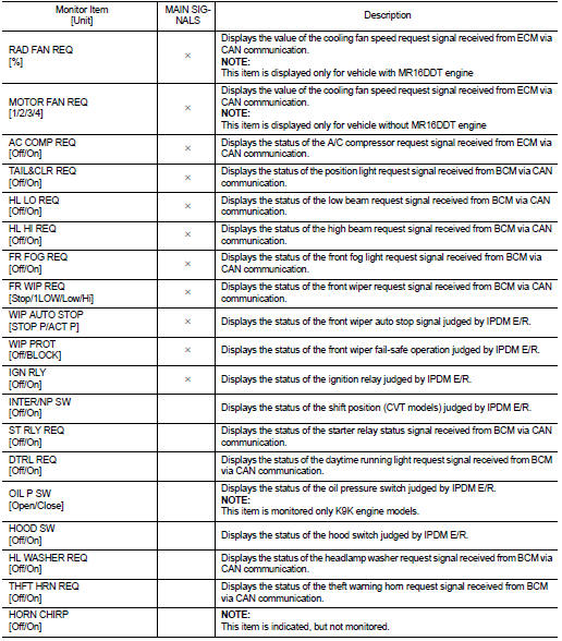
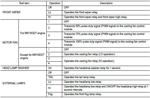
Consult-III Function (IPDM E/R)
APPLICATION ITEM
CONSULT-III performs the following functions via CAN communication with IPDM E/R.

SELF DIAGNOSTIC RESULT
Refer to PCS-55, "DTC Index".
DATA MONITOR
Monitor item
ACTIVE TEST
Test item

 Diagnosis system (ipdm e/r) (with intelligent key system)
Diagnosis Description
AUTO ACTIVE TEST
Description
In auto active test mode, the IPDM E/R sends a drive signal to the following
systems to check their operation.
• Oil pressure warning lamp ...
 Ecu diagnosis informatioN
BCM, IPDM E/R
List of ECU Reference
WITH INTELLIGENT KEY
WITHOUT INTELLIGENT KEY
...
Other materials:
Wiring diagram
CAN SYSTEM
Wiring Diagram
For connector terminal arrangements, harness layouts, and alphabets in a
(option abbreviation; if not
described in wiring diagram), refer to GI-12, "Connector Information/Explanation
of Option Abbreviation".
...
Precaution for Supplemental Restraint System (SRS) "AIR BAG" and "SEAT BELT
PRE-TENSIONER"
The Supplemental Restraint System such as “AIR BAG� and “SEAT BELT PRE-TENSIONER�,
used along
with a front seat belt, helps to reduce the risk or severity of injury to the
driver and front passenger for certain
types of collision. Information necessary to service the system safely is
...
System
WITH AUTO A/C
WITH AUTO A/C : System Diagram
WITH AUTO A/C : System Description
OPERATION DESCRIPTION
• BCM detects that the rear window defogger switch turns ON when the ignition
switch is ON, and then transmits
the rear window defogger switch signal to IPDM E/R via CAN communication for ...
