Nissan Juke Service and Repair Manual : For frontal collision : When SRS is activated in a collision
CAUTION:
Due to varying models and option levels, not all parts listed in the chart below
apply to all vehicles.
WORK PROCEDURE
1. Before performing any of the following steps, ensure that all vehicle body and structural repairs have been completed.
2. Replace the diagnosis sensor unit.
3. Remove the front air bag modules, crash zone sensor, bracket and seat belt pre-tensioner assemblies.
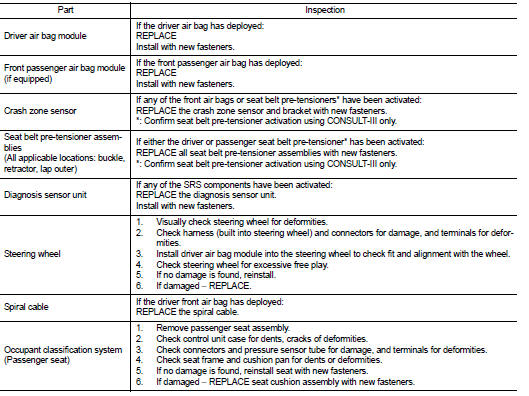
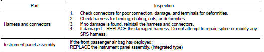
4. Check the SRS components using the table below:
Replace any SRS components showing visible signs of damage. (dents, cracks and
deformation, etc.)
5. Install new front air bag modules, crash zone sensor assembly, bracket and
seat belt pre-tensioner
assemblies.
6. Perform self-diagnosis using CONSULT-III or air bag warning lamp. Refer to SRC-12, "Description" for details. Ensure entire SRS operates properly.
7. After the work is completed, perform self-diagnosis to check that no malfunction is detected. Refer to SRC-12, "Description".
SRS INSPECTION (FOR FRONTAL COLLISION)
 Basic inspection
COLLISION DIAGNOSIS ...
 For frontal collision : When SRS is not activated in a collision
CAUTION:
Due to varying models and option levels, not all parts listed in the chart below
apply to all vehicles.
WORK PROCEDURE
1. Before performing any of the following steps, ensure that all ...
Other materials:
System
System Diagram
System Description
DESCRIPTION
• Automatic air conditioning system is controlled by each function of A/C
auto amp., BCM, ECM and IPDM E/
R.
• Each operation of air conditioning system is transmitted from multi display
unit via CAN communication. A/C
auto amp. transmits ...
Precaution Necessary for Steering Wheel Rotation after Battery Discon
NOTE:
• Before removing and installing any control units, first turn the ignition
switch to the LOCK position, then disconnect
both battery cables.
• After finishing work, confirm that all control unit connectors are connected
properly, then re-connect both
battery cables.
• Always us ...
Final drive
Exploded View
1. Differential side bearing outer race
2. Differential side bearing
3. Final drive
: Replace the parts as a set.
Disassembly
1. Remove differential side bearings, using the drift (A) [SST:
ST33052000] and a puller [Commercial service tool].
Assembly
1. Install different ...
