Nissan Juke Service and Repair Manual : System
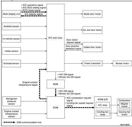
System Diagram
System Description
DESCRIPTION
‚ÄĘ Automatic air conditioning system is controlled by each function of A/C auto amp., BCM, ECM and IPDM E/ R.
‚ÄĘ Each operation of air conditioning system is transmitted from multi display unit via CAN communication. A/C auto amp. transmits each type of indication information to multi display unit via CAN communication. Multi display unit displays each type of indication information that is received.
CONTROL BY A/C AUTO AMP.
‚ÄĘ HAC-18, "Temperature Control" ‚ÄĘ HAC-19, "Air Outlet Control" ‚ÄĘ HAC-19, "Air Flow Control" ‚ÄĘ HAC-20, "Air Inlet Control" ‚ÄĘ HAC-20, "Compressor Control" ‚ÄĘ HAC-21, "Door Control" ‚ÄĘ HAC-24, "ECO Mode Control" ‚ÄĘ Correction for input value
Ambient temperature correction - The A/C auto amp. inputs the temperature detected with the ambient sensor as the ambient temperature.
- Perform the correction of the temperature detected with the ambient sensor for air conditioning control.
- Select and use the initial value of ambient temperature data depending on the engine coolant temperature when turning the ignition switch from OFF to ON. Use the detection temperature of the ambient sensor at low coolant temperature [less than approximately 56¬įC (133¬įF)]. Use the memory data (before the ignition switch is OFF) when the engine is warming up [approximately 56¬įC (133¬įF) or more].
- Do not perform the correction of the ambient temperature when the detection temperature of the ambient temperature is less than approximately −20¬įC (‚Äď4¬įF).
Passenger room temperature correction - The A/C auto amp. inputs the temperature detected with the in-vehicle sensor as the passenger room temperature.
- Perform the correction of the temperature detected with the in-vehicle sensor for air conditioning control.
- The A/C auto amp. performs the correction so that the recognition passenger room temperature changes depending on the difference between the detected passenger room temperature and the recognition passenger room temperature. If the difference is large, the changing is early. The changing becomes slow as the difference becomes small.
Intake temperature correction - The A/C auto amp. inputs the temperature detected with the intake sensor as the intake temperature.
- Perform the correction of the temperature detected with the intake sensor for air conditioning control.
- The A/C auto amp. performs the correction so that the recognition intake temperature changes depending on the difference between the detected intake temperature and the recognition intake temperature. If the difference is large, the changing is early. The changing becomes slow as the difference becomes small.
Sunload amount correction - The A/C auto amp. inputs the sunload amount detected with the sunload sensor.
- Perform the correction of the sunload amount detected with the sunload sensor for air conditioning control.
- When the sunload amount suddenly changes, for example when entering a tunnel, perform the correction so that the recognition sunload amount of the A/C auto amp. changes slowly.
Set temperature correction - A/C auto amp. controls The A/C auto amp. performs the correction to the target temperature set by the temperature control switch so as to match the temperature felt by the passengers depending on the ambient temperature detected with the ambient sensor and controls it so that the interior air temperature is always the most suitable.
CONTROL BY BCM
‚ÄĘ HAC-20, "Compressor Control"
CONTROL BY ECM
‚ÄĘ HAC-20, "Compressor Control"
‚ÄĘ Cooling fan control. Refer to EC-61, "COOLING FAN CONTROL : System
Description".
CONTROL BY IPDM E/R
‚ÄĘ HAC-20, "Compressor Control"
‚ÄĘ Cooling fan control. Refer to PCS-9, "POWER CONTROL SYSTEM : System
Description" (with Intelligent
Key) or PCS-41, "POWER CONTROL SYSTEM : System Description" (without Intelligent
Key).
Temperature Control
‚ÄĘ When ignition switch is in the ON position, A/C auto amp. always automatically controls temperature regardless of air conditioner operational state.
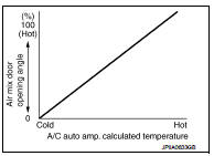
‚ÄĘ A/C auto amp. calculates the target air mix door opening angle depending on set temperature, in-vehicle temperature, ambient temperature, and sunload.
‚ÄĘ Air mix door is controlled depending on the comparison of current air mix door opening angle and target air mix door opening angle.
‚ÄĘ Regardless of in-vehicle temperature, ambient temperature, and sunload, air mix door is fixed at the fully cold position when set temperature is 18¬įC (60¬įF), and at the fully hot position when set temperature is 32¬įC (90¬įF).
Air Outlet Control
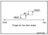
‚ÄĘ While air outlet is in automatic control, A/C auto amp. selects the mode door position depending on a target air mix door angle and outlet air temperature calculated from sunload.
‚ÄĘ If ambient temperature is excessively low, D/F is selected to prevent windshield fogging when air outlet is set to FOOT.
Air Flow Control
DESCRIPTION
‚ÄĘ A/C auto amp. changes duty ratio of blower motor drive signal and controls air flow continuously. When air flow is increased, duty ratio of blower motor drive signal gradually increases to prevent a sudden increase in air flow.
‚ÄĘ In addition to manual control and automatic control, air flow control is compose of starting fan speed control, low coolant temperature starting control, high in-vehicle temperature starting control, and blower speed control at door motor operation.
AUTOMATIC AIR FLOW CONTROL
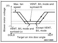
‚ÄĘ A/C auto amp. decides target air flow depending on target air mix door opening angle.
‚ÄĘ A/C auto amp. changes duty ratio of blower motor drive signal and controls air flow continuously so that air flow matches to target air flow.
‚ÄĘ When air outlet is VENT or B/L, the minimum air flow is changed depending on sunload.
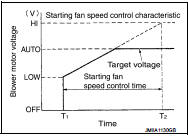
STARTING FAN SPEED CONTROL
When blower motor is activated, A/C auto amp. gradually increases duty ratio of blower fan drive signal to prevent a sudden increase in discharge air flow. (T1 ‚Äď T2 = approximately 10 seconds) NOTE
:
Do not perform the starting air flow control when the discharge outlet
is set to DEF.
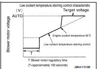
LOW COOLANT TEMPERATURE STARTING CONTROL
If the engine coolant temperature is 56¬įC (133¬įF) or less, to prevent a cold discharged air flow, A/C auto amp. suspends blower motor activation for the maximum 100 seconds depending on target air mix door opening angle. After this, blower fan drive signal is increased gradually, and blower motor is activated.
FAN SPEED CONTROL AT DOOR MOTOR OPERATION
When mode door motor is activated while air flow is more than the specified value, A/C auto amp. reduces temporarily fan speed so that mode door moves smoothly.
HIGH IN- TEMPERATURE STARTING CONTROL
When evaporator temperature is high [intake air temperature sensor value is 35¬įC (95¬įF) or more], to prevent a hot discharged air flow, A/C auto amp. suspends blower motor activation for approximately 3 seconds so that evaporator is cooled by refrigerant.
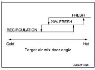
Air Inlet Control
‚ÄĘ While air inlet is in automatic control, A/C auto amp. selects air inlet (fresh air intake, 20% fresh air intake, or recirculation) depending on set temperature, in-vehicle temperature, and ambient temperature.
‚ÄĘ Air inlet is fixed to 80% FRE, only when the conditions are satisfied
as follows:
- Air inlet is FOOT or D/F
- Ambient temperature is 2¬įC (36¬įF) or less
- Maximum fan speed
Compressor Control
DESCRIPTION
‚ÄĘ When the compressor activation condition is satisfied while blower motor is activated, A/C auto amp. transmits A/C ON signal and blower fan ON signal to BCM.
‚ÄĘ BCM transmits the A/C ON signal and blower fan ON signal to ECM via CAN communication line.
- With Intelligent Key system: Refer to BCS-13, "SIGNAL BUFFER SYSTEM : System Description".
- Without Intelligent Key system: Refer to BCS-103, "SIGNAL BUFFER SYSTEM : System Description".
‚ÄĘ ECM judges the conditions of each sensor (Refrigerant pressure sensor signal, accelerator position signal, etc.), and transmits the A/C compressor request signal to IPDM E/R via CAN communication line.
‚ÄĘ By receiving the A/C compressor request signal from ECM, IPDM E/R turns the A/C relay to ON, and activates the compressor.
- With Intelligent Key system: Refer to PCS-6, "RELAY CONTROL SYSTEM : System Description".
- Without Intelligent Key system: Refer to PCS-38, "RELAY CONTROL SYSTEM : System Description".
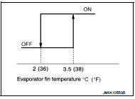
CONTROL BY A/C AUTO AMP.
Low Temperature Protection Control When intake sensor detects that evaporator surface temperature is 2¬įC (36¬įF) or less, A/C auto amp. requests ECM to turn the compressor OFF, and stops the compressor.
When the air temperature returns to 3.5¬įC (38¬įF) or more, the compressor is activated.
CONTROL BY ECM
Compressor Protection Control at Pressure Malfunction The high-pressure side value that is detected by refrigerant pressure sensor is as per the following state, ECM requests IPDM E/R to turn A/C relay OFF and stop the compressor.
‚ÄĘ 3.12 MPa (31.82 kg/cm2, 452.4 psi) or more (When the engine speed is less than
1,500 rpm)
‚ÄĘ 2.74 MPa (27.95 kg/cm2, 397.3 psi) or more (When the engine speed is 1,500 rpm
or more)
‚ÄĘ 0.14 MPa (1.43 kg/cm2, 20.3 psi) or less
Compressor Oil Circulation Control When the engine starts while the engine coolant temperature is 56¬įC (133¬įF) or less, ECM activates the compressor for approximately 6 seconds and circulates the compressor oil once.
Air Conditioning Cut Control When the engine condition is high load, ECM makes the A/C relay to OFF, and stops the compressor. Refer to EC-60, "AIR CONDITIONING CUT CONTROL : System Description".
Door Control
DOOR MOTOR CONTROL
‚ÄĘ A/C auto amp. receives the detection data from each sensor.
‚ÄĘ Intake door motor, when receiving control signal from A/C auto amp. moves intake door to the appropriate position based on the door position detection signal of each PBR (Potentio Balance Resistor).
‚ÄĘ Each motor of air mix and mode, when receiving drive signal from A/C auto amp., moves each door to the appropriate position according to drive signal.
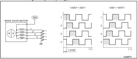
DRIVE METHOD OF STEPPING MOTOR TYPE MOTOR
‚ÄĘ Stepping motor type motor is driven by 4 pieces of drive coil that are sequentially excited.
‚ÄĘ Direction of rotation is changeable by recomposing pattern of excitation.
SWITCH AND THEIR CONTROL FUNCTION
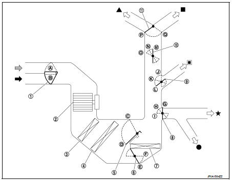
1. Intake door
2. Blower motor
3. Air conditioner filter
4. Evaporator
5. Upper air mix door
6. Lower air mix door
7. Heater core
8. Foot door
9. Side ventilator door
10. Sub defroster door
11. Center ventilator and defroster door
 Fresh air intake
 Recirculation air
 Defroster
 Center ventilator
 Side ventilator
 Foot
Foot
 Rear foot*
*: With rear foot duct
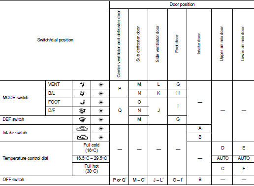
*: Previous setting before turning air conditioning system OFF (FOOT when previous setting is automatic control).
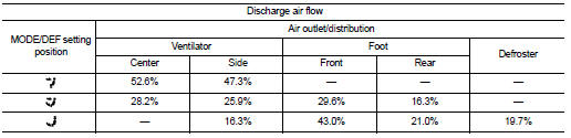
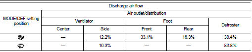
AIR DISTRIBUTION
Without rear foot duct
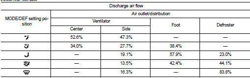
With rear foot duct
ECO Mode Control
DESCRIPTION
‚ÄĘ A/C auto amp. receives operation status of each switch (A/C operation signal), D-MODE setting status (ECO mode signal), and ‚ÄúCLIMATE ECO‚ÄĚ setting status (A/C ECO setting signal) from multi display unit via CAN communication.
‚ÄĘ A/C auto amp. operates air conditioning system in ECO mode, when D-MODE on multi display unit is set to ECO mode while air conditioning system is in automatic control.
NOTE
:
‚ÄĘ For setting procedure of D-MODE, refer to AV-99, "NISSAN DYNAMIC CONTROL
SYSTEM : System
Description".
‚ÄĘ Activation or deactivation of ECO mode can be changed using multi display unit setting function (‚ÄúCLIMATE ECO‚ÄĚ). For setting procedure, refer to AV-99, "NISSAN DYNAMIC CONTROL SYSTEM : System Description".
CONTROL OUTLINE
During ECO mode operation, A/C auto amp. changes air flow and control characteristics of air inlet, within a range that may not spoil the comfort level, lowers operation ratio of compressor, and reduces the electrical load. This reduces engine load and improved fuel economy. Refer to the following items for details of each control.
Air Flow Control
‚ÄĘ A/C auto amp. increases voltage to power transistor gate compared to ordinary
operation and reduces voltage
to blower motor. This reduces air flow.
‚ÄĘ Since air flow is reduced, the amount of air that passes evaporator is reduced. Increase of evaporator temperature can be moderated. Evaporator temperature is easily shifted to temperature control range for low temperature protection control. Operation ratio of evaporator is reduced.
‚ÄĘ Since air flow is reduced, the electrical load is reduced. Alternator power output can be moderated.
Air Inlet Control
‚ÄĘ In the following conditions, A/C auto amp. controls air inlet and increases
recirculation air mixing ratio compared
to ordinary operation.
- Ambient temperature: 25¬įC (77¬įF) or more
- Temperature setting: Any temperature other than full cold (16¬įC) or full hot
(30¬įC)
- Air outlet: In automatic control
- Air flow: In automatic control
- Air inlet: In automatic control or in fresh air intake mode by manual
control
- A/C switch: ON
‚ÄĘ By increasing recirculation air mixing ratio, cooled air in passenger room is circulated in larger amount than during ordinary operation. Air temperature blowing to evaporator is maintained at a low level. Evaporator temperature increase can be moderated. Evaporator temperature is easily shifted to temperature control range for low temperature protection control. Operation ratio of evaporator is reduced.
Fail-safe
FAIL-SAFE FUNCTION
If a communication error exists between the A/C auto amp. and multi display unit for 2 seconds or longer, air conditioning is controlled under the following conditions:
A/C display : OFF
Set temperature : Setting before communication error occurs
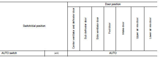
Air outlet : AUTO
Air flow : AUTO
Air inlet : FRE (Fresh air intake)
A/C switch : ON
 Component parts
Component Parts Location
1. BCM
‚ÄĘ With Intelligent Key: Refer to BCS-
6, "BODY CONTROL SYSTEM :
Component Parts Location".
‚ÄĘ Without Intelligent Key: Refer to
BCS-96, "BODY ...
 Operation
Switch Name and Function
OPERATION AND DISPLAY
A/C Display (Display in Multi Display Unit)
‚ÄĘ Air conditioning system operation status is indicated on display in multi
display unit. Indication ...
Other materials:
U1010 control unit (can)
Description
CAN (Controller Area Network) is a serial communication line for real time
application. It is an on-vehicle multiplex
communication line with high data communication speed and excellent error
detection ability. Many electronic
control units are equipped onto a vehicle, and each co ...
Reporting safety defects
For USA
If you believe that your vehicle has a defect which could cause a crash or could
cause injury or death, you should immediately inform the National Highway Traffic
Safety Administration (NHTSA) in addition to notifying NISSAN.
If NHTSA receives similar complaints, it may open an investi ...
Parking brake shoe
Exploded View
1. Anti-rattle pin
2. Back plate
3. Toggle lever
4. Parking brake shoe
5. Brake strut
6. Return spring
7. Spring
8. Adjuster
: Apply PBC (Poly Butyl
Cuprysil) grease or silicone-based grease.
Removal and Installation
REMOVAL
WARNING:
Clean any dust from the parkin ...
