Nissan Juke Service and Repair Manual : P0090 fuel pump
DTC Logic
DTC DETECTION LOGIC
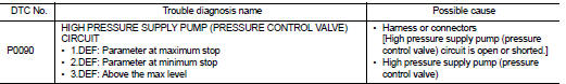
Diagnosis Procedure
1.CHECK HIGH PRESSURE SUPPLY PUMP (PRESSURE CONTROL VALVE) POWER SUPPLY
1. Turn ignition switch OFF.
2. Disconnect high pressure supply pump (pressure control valve) harness connector.
3. Turn ignition switch ON.
4. Check the voltage between high pressure supply pump (pressure control valve) harness connector and ground.
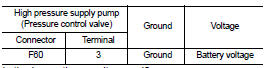
Is the inspection result normal? YES >> GO TO 3.
NO >> GO TO 2.
2.DETECT MALFUNCTIONING PART
Check the following.
• Harness or connectors E8, F1 • Harness for open or short between IPDM E/R and high pressure supply pump (pressure control valve)
>> Repair open circuit or short to ground or short to power in harness or connectors.
3.CHECK HIGH PRESSURE SUPPLY PUMP (PRESSURE CONTROL VALVE) OUTPUT SIGNAL CIRCUIT FOR OPEN AND SHORT
1. Turn ignition switch OFF.
2. Disconnect ECM harness connector.
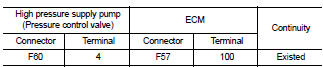
3. Check the continuity between high pressure supply pump (pressure control valve) harness connector and ECM harness connector.
4. Also check harness for short to ground and short to power.
Is the inspection result normal? YES >> GO TO 4.
NO >> Repair open circuit or short to ground or short to power in harness or connectors.
4.HIGH PRESSURE SUPPLY PUMP (PRESSURE CONTROL VALVE) CHECK
Refer to EC-900, "Component Inspection".
Is the inspection result normal? Yes >> GO TO 5.
No >> Replace high pressure supply pump.
5.CHECK INTERMITTENT INCIDENT
Refer to GI-42, "Intermittent Incident", ???INCIDENT SIMULATION TESTS??? and ???GROUND INSPECTION???.
>> INSPECTIO END
Component Inspection
1.CHECK HIGH PRESSURE SUPPLY PUMP (PRESSURE CONTROL VALVE)
1. Turn ignition switch OFF.
2. Disconnect high pressure supply pump (pressure control valve) harness connector.
3. Check resistance between high pressure supply pump (pressure control valve) terminals as follows.
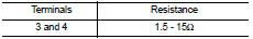
the inspection result normal? YES >> INSPECTION END
NO >> Replace high pressure supply pump.
 P0089 fuel pump
DTC Logic
DTC DETECTION LOGIC
NOTE:
• Conditions for applying the diagnostic procedure to the stored DTCs:
The DTC becomes present during the first 30 seconds after the engine starts.
• In ...
 P0100 MAF sensor
DTC Logic
DTC DETECTION LOGIC
Diagnosis Procedure
1.CHECK GROUND CONNECTIONS
1. Turn ignition switch OFF.
2. Check ground connection E38. Refer to Ground inspection in GI-44, "Circuit
In ...
Other materials:
P0657 ECM relay
DTC Logic
DTC DETECTION LOGIC
NOTE:
When IPDM E/R DTC is indicated with DTC P0657, IPDM E/R DTC must be checked
first.
Diagnosis Procedure
1.CHECK GROUND CONNECTION
1. Turn ignition switch OFF.
2. Check ground connection E38. Refer to Ground Inspection in GI-44, "Circuit
Inspection ...
Timing chain
Exploded View
1. Timing chain slack guide
2. Timing chain tensioner
3. Timing chain
4. Oil pump drive chain
5. Crankshaft sprocket
6. Crankshaft key
7. Oil pump sprocket
8. Front cover
9. O-ring
10. O-ring
11. Oil control valve cover
12. O-ring
13. Oil control valve (EXH)
14 ...
Symptom diagnosis
Squeak and rattle trouble diagnoses
Work Flow
CUSTOMER INTERVIEW
Interview the customer if possible, to determine the conditions that exist
when the noise occurs. Use the Diagnostic
Worksheet during the interview to document the facts and conditions when the
noise occurs and any of
the cu ...
