
Nissan Juke Service and Repair Manual : P0100 MAF sensor
DTC Logic
DTC DETECTION LOGIC

Diagnosis Procedure
1.CHECK GROUND CONNECTIONS
1. Turn ignition switch OFF.
2. Check ground connection E38. Refer to Ground inspection in GI-44, "Circuit Inspection".
Is the inspection result normal? YES >> GO TO 2.
NO >> Repair or replace ground connection.
2.CHECK MASS AIR FLOW SENSOR POWER SUPPLY CIRCUIT-I
1. Turn ignition switch OFF.
2. Disconnect mass air flow sensor harness connector.
3. Turn ignition switch ON.
4. Check the voltage between mass air flow sensor harness connector and ground.
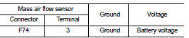
Is the inspection result normal? YES >> GO TO 4.
NO >> GO TO 3.
3.DETECT MALFUNCTIONING PART
Check the following.
• Harness connectors E8, F1 • Harness for open or short between IPDM E/R and mass air flow sensor
>> Repair open circuit or short to ground or short to power in harness or connectors.
4.CHECK MASS AIR FLOW SENSOR GROUND CIRCUIT FOR OPEN AND SHORT
1. Turn ignition switch OFF.
2. Disconnect ECM harness connectors.
3. Check the continuity between mass air flow sensor harness connector and ECM harness connector.

4. Also check harness for short to ground and short to power.
Is the inspection result normal? YES >> GO TO 5.
NO >> Repair open circuit or short to ground or short to power in harness or connectors.
5.CHECK MASS AIR FLOW SENSOR NPUT SIGNAL CIRCUIT FOR OPEN AND SHORT
1. Check the continuity between mass air flow sensor harness connector and ECM harness connector.

2. Also check harness for short to ground and short to power.
Is the inspection result normal? YES >> GO TO 6.
NO >> Repair open circuit or short to ground or short to power in harness or connectors.
6.CHECK MASS AIR FLOW SENSOR
Refer to EC-902, "Component Inspection".
Is the inspection result normal? YES >> GO TO 7.
NO >> Replace mass air flow sensor.
7.CHECK INTERMITTENT INCIDENT
Refer to GI-42, "Intermittent Incident", ???INCIDENT SIMULATION TESTS??? and ???GROUND INSPECTION???.
>> INSPECTION END
Component Inspection
1.CHECK MASS AIR FLOW SENSOR
1. Turn ignition switch OFF.
2. Reconnect all harness connectors disconnected.
3. Turn ignition switch ON.
4. Check the voltage between mass air flow sensor harness connector.

Is the inspection result normal? YES >> INSPECTION END
NO >> Replace mass air flow sensor
 P0090 fuel pump
DTC Logic
DTC DETECTION LOGIC
Diagnosis Procedure
1.CHECK HIGH PRESSURE SUPPLY PUMP (PRESSURE CONTROL VALVE) POWER SUPPLY
1. Turn ignition switch OFF.
2. Disconnect high pressure supply pump (p ...
 P0101 MAF sensor
DTC Logic
DTC DETECTION LOGIC
Diagnosis Procedure
1.CHECK AIR FILTER
Check that air filter is not obstructed.
Is the inspection result normal?
Yes >> Repair or replace.
No >> ...
Other materials:
Front passenger air bag module
Exploded View
1. Front passenger air bag module
2. Instrument panel assembly
: Pawl
: Do not reuse
: N·m (kg-m, ft-lb)
Removal and Installation
WARNING:
• Before servicing, turn ignition switch OFF, disconnect battery negative
terminal and wait 3 minutes
or more.
• Always work fr ...
P0611 ECM protection
Description
This DTC is detected when the ECM protective function is activated due to an
extreme temperature increase
in ECM, resulting from severe conditions such as heavy load driving.
DTC Logic
DTC DETECTION LOGIC
DTC CONFIRMATION PROCEDURE
1.PERFORM DTC CONFIRMATION PROCEDURE
This DTC ...
Diagnosis and repair work flow
WorkFlow
DETAILED FLOW
1.OBTAIN INFORMATION ABOUT SYMPTOM
Interview the customer to obtain the malfunction information (conditions and
environment when the malfunction
occurred) as much as possible when the customer brings the vehicle in.
>> GO TO 2.
2.REPRODUCE THE MALFUNCTION INF ...
