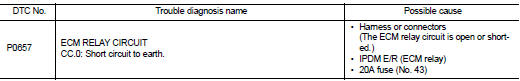
Nissan Juke Service and Repair Manual : P0657 ECM relay
DTC Logic
DTC DETECTION LOGIC
NOTE
:
When IPDM E/R DTC is indicated with DTC P0657, IPDM E/R DTC must be checked
first.
Diagnosis Procedure
1
.CHECK GROUND CONNECTION
1. Turn ignition switch OFF.
2. Check ground connection E38. Refer to Ground Inspection in GI-44, "Circuit Inspection".
Is the inspection result normal? YES >> GO TO 2.
NO >> Repair or replace ground connection.
2.CHECK ECM RELAY CIRCUIT-I
Check the voltage between ECM harness connector and ground.
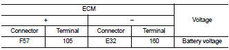
Is the inspection result normal? YES >> GO TO 6.
NO >> GO TO 3.
3.CHECK ECM RELAY CIRCUIT-II
1. Disconnect ECM harness connector F57.
2. Disconnect IPDM E/R harness connector E14.
3. Check the continuity between ECM harness connector and IPDM E/R harness connector.
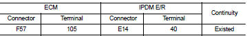
4. Also check harness for short to ground and short to power.
Is the inspection result normal? YES >> GO TO 5.
NO >> GO TO 4.
4.DETECT MALFUNCTIONING PART
Check the following.
• Harness or connectors E8, F1 • Harness for open or short between ECM and IPDM E/R
>> Repair open circuit or short to ground or short to power in harness or connectors.
5.CHECK 20A FUSE
1. Disconnect 20A fuse (No. 43) from IPDM E/R.
2. Check 20A fuse.
Is the inspection result normal? YES >> GO TO 6.
NO >> Replace 20A fuse.
6.CHECK INTERMITTENT INCIDENT
Refer to GI-42, "Intermittent Incident".
>> INSPECTION END
 P0651 sensor power supply
DTC Logic
DTC DETECTION LOGIC
Diagnosis Procedure
1.CHECK GROUND CONNECTION
1. Turn ignition switch OFF.
2. Check ground connection E38. Refer to Ground Inspection in GI-44, "Circuit
Ins ...
 P0697 sensor power supply
DTC Logic
DTC DETECTION LOGIC
Diagnosis Procedure
1.CHECK GROUND CONNECTION
1. Turn ignition switch OFF and wait at least 4 minutes.
2. Check ground connection E38. Refer to Ground Inspection i ...
Other materials:
Intelligent Keys (if so equipped)
Your vehicle can only be driven with the Intelligent Keys which are registered
to your vehicle’s Intelligent Key system components and NISSAN Vehicle Immobilizer
System components.
As many as 4 Intelligent Keys can be registered and used with one vehicle. The
new keys must be registered by ...
P1832 TCS operation signal
DTC Logic
DTC DETECTION LOGIC
DTC CONFIRMATION PROCEDURE
1.DTC REPRODUCTION PROCEDURE
With CONSULT-III
1. Start the engine and drive at 30 km/h (19 MPH) or more.
2. Perform self-diagnosis for “ALL MODE AWD/4WD”.
Is DTC “P1832” detected?
YES >> Proceed to diagnosis procedure ...
USB/iPod charging ports
Type-A USB connection and charging port
There are dedicated USB/iPod charging ports conveniently located behind the center console for rear passengers. These ports are designed to charge compatible devices and mobile phones quickly while traveling in your N ...
