Nissan Juke Service and Repair Manual : P0697 sensor power supply
DTC Logic
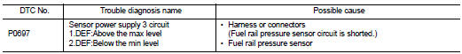
DTC DETECTION LOGIC
Diagnosis Procedure
1.CHECK GROUND CONNECTION
1. Turn ignition switch OFF and wait at least 4 minutes.
2. Check ground connection E38. Refer to Ground Inspection in GI-44, "Circuit Inspection".
Is the inspection result normal? YES >> GO TO 2.
NO >> Repair or replace ground connection.
2.CHECK FUEL RAIL PRESSURE SENSOR POWER SUPPLY CIRCUIT-I
1. Disconnect fuel rail pressure sensor harness connector.
2. Turn ignition switch ON.
3. Check the voltage between fuel rail pressure sensor harness connector and ground.
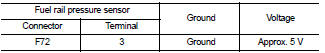
Is the inspection result normal? YES >> GO TO 4.
NO >> GO TO 3.
3.CHECK FUEL RAIL PRESSURE SENSOR POWER SUPPLY CIRCUIT-II
1. Turn ignition switch OFF and wait at least 4 minutes.
2. Disconnect ECM harness connectors.
3. Check harness for short to power and short to ground between fuel rail pressure sensor harness connector and ECM harness connector.
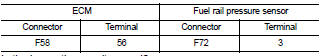
Is the inspection result normal? YES >> GO TO 4.
NO >> Repair short to ground or short to power in harness or connectors.
4.CHECK FUEL RAIL PRESSURE SENSOR
Refer to EC-918, "Component Inspection".
Is the inspection result normal? YES >> GO TO 5.
NO >> Replace fuel rail.
5.CHECK INTERMITTENT INCIDENT
Refer to GI-42, "Intermittent Incident".
>> INSPECTION END
 P0657 ECM relay
DTC Logic
DTC DETECTION LOGIC
NOTE:
When IPDM E/R DTC is indicated with DTC P0657, IPDM E/R DTC must be checked
first.
Diagnosis Procedure
1.CHECK GROUND CONNECTION
1. Turn ignition switch O ...
 P0833 CPP switch
DTC Logic
DTC DETECTION LOGIC
Diagnosis Procedure
1.CHECK CLUTCH PEDAL POSITION SWITCH GROUND CIRCUIT FOR OPEN AND SHORT
1. Turn ignition switch OFF.
2. Disconnect clutch pedal position switch ...
Other materials:
Service Notice or Precautions for EPS System
• Check the following item when performing the trouble diagnosis.
- Check any possible causes by interviewing the symptom and it′s condition from
the customer if any malfunction,
such as EPS warning lamp is turned ON, occurs.
- Check if air pressure and size of tires are proper, the s ...
B2627 outside antenna
DTC Logic
DTC DETECTION LOGIC
DTC CONFIRMATION PROCEDURE
1.PERFORM DTC CONFIRMATION PROCEDURE
1. Disconnect outside key antenna (passenger side) connector.
2. Perform “INTELLIGENT KEY” Self Diagnostic Result.
Is outside key antenna DTC detected?
YES >> Refer to DLK-238, "Di ...
Removal and installation
Exhaust system
Exploded View
2WD
1. Center muffler
2. Mounting rubber
3. Spring
4. Seal bearing
5. Stud bolt
6. Three way catalyst
7. Heated oxygen sensor 2
8. Seal bearing
9. Ring gasket
10. Main muffler
A. To catalyst convertor
: N·m (kg-m, ft-lb)
: Always replace after eve ...
