Nissan Juke Service and Repair Manual : P0745 pressure control solenoid A
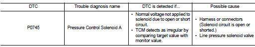
DTC Logic
DTC DETECTION LOGIC
DTC CONFIRMATION PROCEDURE
NOTE
:
If ÔÇťDTC CONFIRMATION PROCEDUREÔÇŁ has been previously performed, always turn
ignition switch
OFF and wait at least 10 seconds before performing the next test.
After the repair, perform the following procedure to confirm the malfunction is eliminated.
1.CHECK DTC DETECTION
 With CONSULT-III
1. Turn ignition switch ON.
2. Start engine and wait at least 5 seconds.
3. Select ÔÇťSelf Diagnostic ResultsÔÇŁ in ÔÇťTRANSMISSIONÔÇŁ.
 With GST
Follow the procedure ÔÇťWith CONSULT-IIIÔÇŁ.
Is ÔÇťP0745ÔÇŁ detected? YES >> Go to TM-219, "Diagnosis Procedure".
NO >> Check intermittent incident. Refer to GI-42, "Intermittent Incident".
Diagnosis Procedure
1.CHECK LINE PRESSURE SOLENOID VALVE CIRCUIT
1. Turn ignition switch OFF.
2. Disconnect TCM connector.
3. Check resistance between TCM connector terminal and ground.
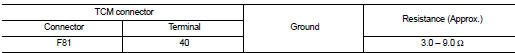
Is the inspection result normal? YES >> GO TO 4.
NO >> GO TO 2.
2.CHECK LINE PRESSURE SOLENOID VALVE
Check line pressure solenoid valve. Refer to TM-220, "Component Inspection" Is the inspection result normal? YES >> GO TO 3.
NO >> Repair or replace damaged parts.
3. CHECK HARNESS BETWEEN TCM AND LINE PRESSURE SOLENOID VALVE
1. Turn ignition switch OFF.
2. Disconnect CVT unit harness connector and TCM connector.
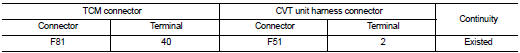
3. Check continuity between TCM connector terminal and CVT unit harness connector terminal.
4. If OK, check harness for short to ground and short to power.
5. If OK, check continuity between ground and CVT assembly.
6. Reinstall any part removed.
Is the inspection result normal? YES >> GO TO 4.
NO >> Repair or replace damaged parts.
4.CHECK TCM
Check TCM input/output signals. Refer to TM-164, "Reference Value".
Is the inspection result normal? YES >> Check intermittent incident. Refer to GI-42, "Intermittent Incident".
NO >> Replace the TCM. Refer to TM-280, "Removal and Installation".
Component Inspection
LINE PRESSURE SOLENOID VALVE
1.LINE PRESSURE SOLENOID VALVE
1. Turn ignition switch OFF.
2. Disconnect CVT unit harness connector.
3. Check resistance between CVT unit harness connector terminal and ground.
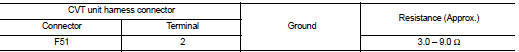
Is the inspection result normal? YES >> INSPECTION END
NO >> Replace the transaxle assembly. Refer to TM-301, "Removal and Installation"
 P0744 torque converter
Description
This malfunction is detected when the torque converter clutch does not
lock-up as instructed by the TCM. This
is not only caused by electrical malfunction (circuits open or shorted), b ...
 P0746 pressure control solenoid A
Description
The line pressure solenoid valve regulates the oil pump discharge pressure to
suit the driving condition in
response to a signal sent from the TCM.
DTC Logic
DTC DETECTION LOGIC
D ...
Other materials:
Light & rain sensor
Component Function Check
1.CHECK LIGHT & RAIN SENSOR
1. Clean light & rain sensor detection area of windshield fully.
2. Turn ignition switch ON.
3. Turn lighting switch AUTO.
4. With the light & rain sensor illuminating, check the auto light function.
Is the inspection result no ...
ECU diagnosis information
ECM
Reference Value
VALUES ON THE DIAGNOSIS TOOL
Remarks:
ÔÇó Specification data are reference values.
ÔÇó Specification data are output/input values which are detected or supplied by
the ECM at the connector.
*Specification data may not be directly related to their components
signals/valu ...
Key reminder function does not operate
Diagnosis Procedure
1.CHECK DTC WITH BCM
Check that DTC is not detected with BCM.
Is the inspection result normal?
YES >> GO TO 2.
NO >> Refer to BCS-67, "DTC Index".
2.CHECK ÔÇťANTI KEY LOCK IN FUNCTIÔÇŁ SETTING IN ÔÇťWORK SUPPORTÔÇŁ
1. Select ÔÇťINTELLIGENT KEYÔÇ ...
