Nissan Juke Service and Repair Manual : MR16DDT : Exploded View
REMOVAL
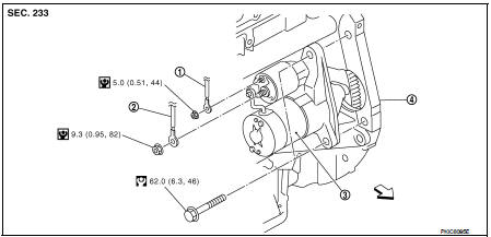
1. ÔÇťSÔÇŁ terminal harness
2. ÔÇťBÔÇŁ terminal harness
3. Starter motor
4. Cylinder block
 : Vehicle front
 : N┬Ěm (kg-m, in-lb)
 : N┬Ěm (kg-m, ft-lb)
DISASSEMBLY
Type: S114-902
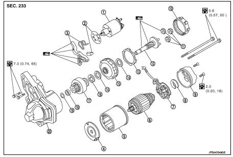
1. Magnetic switch assembly
2. Dust cover kit
3. Shift lever set
4. Center bracket (A)
5. Yoke assembly
6. Armature assembly
7. Brush holder assembly
8. Thrust washer
9. Rear cover assembly
10. Internal gear
11. Planetary gear
12. Pinion shaft
13. Packing
14. Thrust washer
15. Center bracket (P)
16. E-ring
17. Pinion assembly
18. Pinion stopper
19. Pinion stopper clip
20. Gear case assembly
 : N┬Ěm (kg-m, in-lb)
 : High-temperature grease point
Type: S114-955
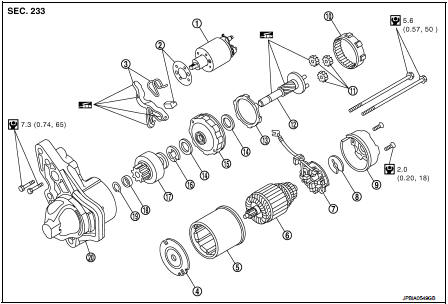
1. Magnetic switch assembly
2. Dust cover kit
3. Shift lever set
4. Center bracket (A)
5. Yoke assembly
6. Armature assembly
7. Brush holder assembly
8. Thrust washer
9. Rear cover assembly
10. Internal gear
11. Planetary gear
12. Pinion shaft
13. Packing
14. Thrust washer
15. Center bracket (P)
16. E-ring
17. Pinion assembly
18. Pinion stopper
19. Pinion stopper clip
20. Gear case assembly
 : N┬Ěm (kg-m, in-lb)
 : High-temperature grease point
NOTE
:
Apply high-temperature grease to lubricate the bearing, gears and frictional
surface when assembling the
starter.
 HR16DE : Inspection and Adjust
INSPECTION
Magnetic Switch Check
ÔÇó Before starting to check, disconnect the battery cable from the negative
terminal.
ÔÇó Disconnect ÔÇťMÔÇŁ terminal of starter motor.
1. Continuity test [be ...
 MR16DDT : Removal and Installation
REMOVAL
1. Disconnect the battery cable from the negative terminal. Refer to PG-124,
"Removal and Installation".
2. Drain engine coolant from radiator. Refer to CO-11, "Draining&quo ...
Other materials:
Precaution
Precaution for Supplemental Restraint System (SRS) "AIR BAG" and "SEAT
BELT
PRE-TENSIONER"
The Supplemental Restraint System such as ÔÇťAIR BAGÔÇŁ and ÔÇťSEAT BELT PRE-TENSIONERÔÇŁ,
used along
with a front seat belt, helps to reduce the risk or severity of injury to the
...
Fuel injector and fuel tube
Exploded View
1. Holder
2. Seal ring (white)
3. Backup ring
4. O-ring (blue)
5. Fuel injector
6. Stud bolt
7. Fuel tube assembly
8. Fuel tube insulator
9. Fuel tube protector
10. Fuel pressure sensor
11. O-ring
12. Fuel tube adaptor
13. Backup ring (white)
14. Backup ring ( ...
B1074, B1075, B1076, B1077, B1078, B1079 diagnosis sensor unit
DTC Logic
DTC DETECTION LOGIC
DTC CONFIRMATION PROCEDURE
1.CHECK SELF-DIAG RESULT
With CONSULT-III
1. Turn ignition switch ON.
2. Perform ÔÇťSelf Diagnostic ResultÔÇŁ mode of ÔÇťAIR BAGÔÇŁ using CONSULT-III.
Without CONSULT-III
1. Turn ignition switch ON.
2. Check the air bag warning la ...
