Nissan Juke Service and Repair Manual : HR16DE : Inspection and Adjust
INSPECTION
Magnetic Switch Check • Before starting to check, disconnect the battery cable from the negative terminal.
• Disconnect “M” terminal of starter motor.
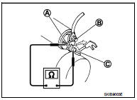
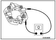
1. Continuity test [between “S” terminal (A) and switch body]
B : “B” terminal
C : “M” terminal
• Replace magnetic switch if continuity does not exist.
![2. Continuity test [between “S” terminal (A) and “M” terminal (C)]](images/books/335/22/index259.jpg)
2. Continuity test [between “S” terminal (A) and “M” terminal (C)]
B : “B” terminal
• Replace magnetic switch if continuity does not exist.
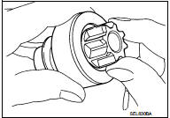
Pinion/Clutch Check
1. Inspect pinion teeth.
• Replace pinion if teeth are worn or damaged. (Also check condition of ring gear teeth.) 2. Inspect reduction gear teeth (If equipped).
• Replace reduction gear if teeth are worn or damaged. (Also check condition of armature shaft gear teeth.) 3. Check to see if pinion locks in one direction and rotates smoothly in the opposite direction.
• Replace pinion assembly if it is locked or rotated in both directions or unusual resistance is evident.
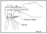
Brush Check
• Check wear of brush.
Minimum length of brush : Refer to SDS STR-35, "Starter Motor".
• Replace brush if the measurement value is less than the specified value.
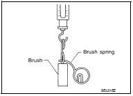
Brush Spring Check
• Check brush spring tension with brush spring detached from
brush.
Spring tension (with new brush) : Refer to SDS STR-35, "Starter Motor".
• Replace brush spring if the measurement value is less than the specified value.
Brush Holder Check
1. Perform insulation test between brush holder (positive side) and
its base (negative side).
• Replace brush holder assembly if continuity does not exist.
2. Check brush to see if it moves smoothly.
• If brush holder is bent, replace it; if sliding surface is dirty, clean.
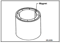
Yoke Check
Magnet is secured to yoke by bonding agent. Check magnet to see
that it is secured to yoke and for any cracks. Replace malfunctioning
parts as an assembly.
CAUTION:
Never clamp yoke in a vise or strike it with a hammer.
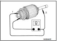
Armature Check
1. Continuity test (between two segments side by side)
• Replace armature assembly if continuity does not exist.
2. Insulation test (between each commutator bar and shaft) • Replace armature assembly if continuity exists.
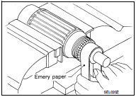
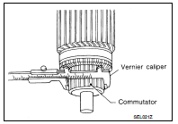
3. Check commutator surface.
• Grind with No. 500 - 600 emery paper if it has a rough surface.
4. Check diameter of commutator.
Commutator minimum diameter : Refer to SDS STR-35, "Starter Motor".
• Replace armature assembly if the measurement value is less than the specified value.
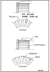
5. Check depth of insulating mold from commutator surface.
• Undercut to 0.5 to 0.8 mm (0.020 to 0.031 in) if the depth is 0.2 mm (0.008 in) or less.
ADJUSTMENT
Pinion Protrusion Length Adjustment
CLEARANCE
• With pinion driven out by magnetic switch, push pinion back to remove slack and measure clearance “L” between the front edge of the pinion and the pinion stopper.
Clearance “L” : Refer to SDS STR-35, "Starter Motor".
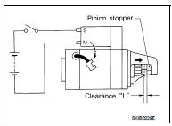
• Adjust with the adjusting plate if the measurement value is not in the specified area.
 HR16DE : Removal and Installation
REMOVAL
1. Disconnect the battery cable from the negative terminal. Refer to PG-124,
"Removal and Installation".
2. Remove radiator reservoir tank. Refer to CO-17, "Exploded View&qu ...
 MR16DDT : Exploded View
REMOVAL
1. “S” terminal harness
2. “B” terminal harness
3. Starter motor
4. Cylinder block
: Vehicle front
: N·m (kg-m, in-lb)
: N·m (kg-m, ft-lb)
DISASSEMBLY
Type: S114-902
...
Other materials:
Removal and installation
IPDM E/R
Exploded View
1. IPDM E/R cover A
2. IPDM E/R
3. IPDM E/R cover B
Removal and Installation
CAUTION:
IPDM E/R integrated relays are not serviceable parts, and must not be removed
from the unit.
REMOVAL
1. Remove battery.
2. Press and expand pawls (A) on lateral side of IPDM E ...
Diagnosis system (BCM) (with intelligent key system)
Description
Air conditioning system performs self-diagnosis, operation check, function
diagnosis, and various settings
using diagnosis function of each control unit.
Common item : consult-III Function (BCM - COMMON ITEM)
APPLICATION ITEM
CONSULT-III performs the following functions via CAN ...
Unit removal and installation
Engine assembly
Exploded View
1. Engine mounting assembly (RH)
2. Rear engine mounting bracket
3. Rear torque rod
4. Engine mounting bracket (LH)
5. Stud bolt
6. Engine mounting bracket (LH)
7. Engine mounting insulator (LH)
8. Mass damper
: N·m (kg-m, ft-lb)
CAUTION:
Check tha ...
