Nissan Juke Service and Repair Manual : HR16DE : Removal and Installation
REMOVAL
1. Disconnect the battery cable from the negative terminal. Refer to PG-124, "Removal and Installation".
2. Remove radiator reservoir tank. Refer to CO-17, "Exploded View".
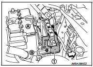
3. Disconnect harness connectors (1) from battery terminal with fusible link.
4. Remove harness fixing clips (A) from F/L·fuse holder bracket.
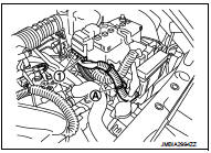
5. Remove harness fixing clips (A) from F/L·fuse holder bracket.
6. Disconnect harness connector (1) from ECM.
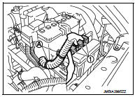
7. Disengage pawl using a flat-bladed screwdriver (A). Remove F/ L·fuse holder.
 : Vehicle front
8. Move F/L·fuse holder and harness to a location where they do not inhibit work.
9. Remove harness fixing clips (A) from F/L·fuse holder bracket.
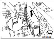
10. Remove mounting bolt (A) and nut (B) of F/L·fuse holder bracket (1), and then remove F/L·fuse holder bracket.
 : Vehicle front
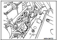
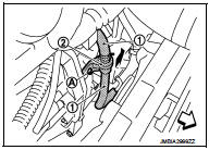
11. Remove mounting bolt (A), and then move water hose (1) and heater thermostat (2) to a location where they do not inhibit work (CVT models).
 : Vehicle front
12. Remove “B” terminal nut and “B” terminal harness.
13. Remove “S” terminal nut and “S” terminal harness.
14. Remove starter motor mounting bolts.
15. Remove starter motor towards vehicle upper.
INSTALLATION
Note the following item, and then install in the reverse order of removal.
CAUTION:
Be careful to tighten “B” terminal nut to the specified torque.
 HR16DE : Exploded View
REMOVAL
1. Cylinder block
2. “B” terminal harness
3. “S” terminal harness
4. Starter motor
: Vehicle front
: N·m (kg-m, in-lb)
: N·m (kg-m, ft-lb)
DISASSEMBLY
Type: M000T32172ZE ...
 HR16DE : Inspection and Adjust
INSPECTION
Magnetic Switch Check
• Before starting to check, disconnect the battery cable from the negative
terminal.
• Disconnect “M” terminal of starter motor.
1. Continuity test [be ...
Other materials:
B2603 shift position
DTC Logic
DTC DETECTION LOGIC
NOTE:
• If DTC B2603 is displayed with DTC B2601, first perform the trouble diagnosis
for DTC B2601. Refer to
SEC-79, "DTC Logic".
DTC CONFIRMATION PROCEDURE
1.PERFORM DTC CONFIRMATION PROCEDURE 1
1. Shift the selector lever to the P position.
2. ...
Conventional (fixed speed) cruise control mode
Note: In the conventional (fixed speed) cruise control mode, the ProPILOT Assist system provides no approach warnings, automatic emergency braking, or active steering assistance.
This mode allows you to maintain a steady driving speed between 25 and 90 mph (40 to 144 km/h) without needing to ke ...
Clutch piping
Exploded View
RS5F92R
1. CSC (Concentric Slave Cylinder)
2. Clutch tube
3. Clutch damper
4. Bracket
5. Master cylinder
RS6F94R
1. CSC (Concentric Slave Cylinder)
2. Clutch tube
3. Clutch damper
4. Bracket
5. Master cylinder
Hydraulic Layout
1. Clutch tube
2. Lock pin
3. ...
