Nissan Juke Service and Repair Manual : B2562 low voltage
DTC Logic
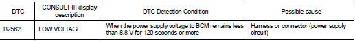
DTC DETECTION LOGIC
DTC CONFIRMATION PROCEDURE
1.DTC CONFIRMATION
1. Erase DTC.
2. Turn ignition switch OFF.
3. Perform the “Self Diagnostic Result” of BCM with CONSULT-III, when passed 120 seconds or more after the ignition switch is turned ON.
Is any DTC detected? YES >> Refer to BCS-86, "Diagnosis Procedure".
NO >> INSPECTION END
Diagnosis Procedure
1.CHECK POWER SUPPLY CIRCUIT
Check BCM power supply circuit. Refer to BCS-87, "Diagnosis Procedure".
Is the circuit normal? YES >> Replace BCM. Refer to BCS-93, "Removal and Installation".
NO >> Repair the malfunctioning part.
 U0415 vehicle speed
Description
U0415 is displayed if any unusual condition is present in the reception
status of the vehicle speed signal from
the ABS actuator and electric unit (control unit).
DTC Logic
DTC DETEC ...
 Power supply and ground circuit
Diagnosis Procedure
1.CHECK FUSE AND FUSIBLE LINK
Check that the following fuse and fusible link are not blown.
Is the fuse fusing?
YES >> Replace the blown fuse or fusible link after repa ...
Other materials:
Units
• The UNITS given in this manual are primarily expressed as the SI UNIT
(International System of Unit), and
alternatively expressed in the metric system and in the yard/pound system.
Also with regard to tightening torque of bolts and nuts, there are descriptions
both about range and about ...
P0075 IVT control solenoid valve
DTC Logic
DTC DETECTION LOGIC
DTC CONFIRMATION PROCEDURE
1.PRECONDITIONING
If DTC Confirmation Procedure has been previously conducted, always turn
ignition switch OFF and wait at
least 10 seconds before conducting the next test.
>> GO TO2.
2.PERFORM DTC CONFIRMATION PROCEDURE
...
S terminal circuit
Description
The output voltage of the alternator is controlled by the IC voltage
regulator at the “S” terminal detecting the
input voltage.
The “S” terminal circuit detects the battery voltage to adjust the alternator
output voltage with the IC voltage
regulator.
Diagnosis Procedu ...
