Nissan Juke Service and Repair Manual : Power supply and ground circuit
Diagnosis Procedure
1.CHECK FUSE AND FUSIBLE LINK
Check that the following fuse and fusible link are not blown.

Is the fuse fusing? YES >> Replace the blown fuse or fusible link after repairing the affected circuit if a fuse or fusible link is blown.
NO >> GO TO 2.
2.CHECK POWER SUPPLY CIRCUIT
1. Turn ignition switch OFF.
2. Disconnect BCM connectors.
3. Check voltage between BCM harness connector and ground.
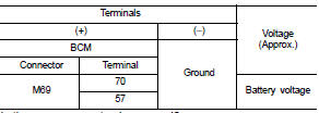
Is the measurement value normal? YES >> GO TO 3.
NO >> Repair harness or connector.
3.CHECK GROUND CIRCUIT
Check continuity between BCM harness connector and ground.
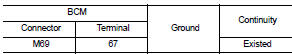
Does continuity exist? YES >> INSPECTION END
NO >> Repair harness or connector.
 B2562 low voltage
DTC Logic
DTC DETECTION LOGIC
DTC CONFIRMATION PROCEDURE
1.DTC CONFIRMATION
1. Erase DTC.
2. Turn ignition switch OFF.
3. Perform the “Self Diagnostic Result” of BCM with CONSULT-III, when ...
 Combination switch output circuit
Diagnosis Procedure
1.CHECK OUTPUT 1 - 5 CIRCUIT FOR OPEN
1. Turn ignition switch OFF.
2. Disconnect BCM and combination switch connectors.
3. Check continuity between BCM harness connector and co ...
Other materials:
Charging timer
Optimize your energy management and utility costs by utilizing the charging timer feature of the Nissan Leaf. This function allows you to create custom schedules for your vehicle's Li-ion battery charging cycles. Once you have established your preferred schedule, the Nissan Leaf will automatically c ...
Blind Spot Warning (BSW)
WARNING
Failure to strictly adhere to the safety warnings and operational instructions for the proper use of the Blind Spot Warning (BSW) system could result in a collision, potentially causing serious injury or death.
The BSW system is intended to supplement, not replace, standa ...
Remote keyless entry receiver
Component Function Check
1.CHECK FUNCTION
1. Select “DOOR LOCK” of “BCM” using CONSULT-III.
2. Select “KEYLESS ” or “KEYLESS UNLOCK” in “DATA MONITOR” mode.
3. Check that the function operates normally according to the following
conditions.
Is the inspection result norma ...
