Nissan Juke Service and Repair Manual : Combination switch output circuit
Diagnosis Procedure
1.CHECK OUTPUT 1 - 5 CIRCUIT FOR OPEN
1. Turn ignition switch OFF.
2. Disconnect BCM and combination switch connectors.
3. Check continuity between BCM harness connector and combination switch harness connector.
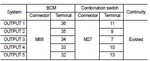
Does continuity exist? YES >> GO TO 2.
NO >> Repair harnesses or connectors.
2.CHECK OUTPUT 1 - 5 CIRCUIT FOR SHORT
Check for continuity between BCM harness connector and ground.
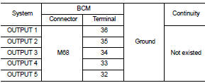
Does continuity exist? YES >> Repair harnesses or connectors.
NO >> GO TO 3.
3.CHECK BCM OUTPUT VOLTAGE
1. Connect BCM connector.
2. Check voltage between BCM harness connector and ground.
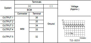
Is the measurement value normal?
YES >> Replace combination switch.
NO >> Replace BCM. Refer to BCS-93, "Removal and Installation".
 Power supply and ground circuit
Diagnosis Procedure
1.CHECK FUSE AND FUSIBLE LINK
Check that the following fuse and fusible link are not blown.
Is the fuse fusing?
YES >> Replace the blown fuse or fusible link after repa ...
 Combination switch input circuit
Diagnosis Procedure
1.CHECK INPUT 1 - 5 CIRCUIT FOR OPEN
1. Turn ignition switch OFF.
2. Disconnect BCM and combination switch connectors.
3. Check continuity between BCM harness connector and com ...
Other materials:
U1119 lost comm (multi-display)
Description
CAN (Controller Area Network) is a serial communication line for real-time
application. It is an on-vehicle multiplex
communication line with high data communication speed and excellent malfunction
detection ability.
Many electronic control units are equipped onto a vehicle, and ...
Electric controlled coupling
Exploded View
1. Filler plug
2. Gasket
3. Drain plug
4. Breather tube
5. Clip
6. Breather hose
7. Breather
8. sub-harness clip
9. sub-harness
10. Rear cover
11. Center stem
12. Side bearing (right)
13. Side bearing adjusting shim (right)
14. Side oil seal (right)
15. Conne ...
B2190 nats antenna AMP
DTC Logic
DTC DETECTION LOGIC
DTC CONFIRMATION PROCEDURE
1.PERFORM DTC CONFIRMATION PROCEDURE
1. Turn ignition switch ON.
2. Check DTC in “Self Diagnostic Result” mode of “BCM” using CONSULT-III.
Is DTC detected?
YES >> Refer to SEC-200, "Diagnosis Procedure".
N ...
