Nissan Juke Service and Repair Manual : B2190 nats antenna AMP
DTC Logic
DTC DETECTION LOGIC
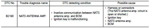
DTC CONFIRMATION PROCEDURE
1.PERFORM DTC CONFIRMATION PROCEDURE
1. Turn ignition switch ON.
2. Check DTC in “Self Diagnostic Result” mode of “BCM” using CONSULT-III.
Is DTC detected? YES >> Refer to SEC-200, "Diagnosis Procedure".
NO >> INSPECTION END
Diagnosis Procedure
1.CHECK FUSE
Check that the following IPDM E/R fuse is not blown.

Is the fuse fusing? YES >> Replace the blown fuse after repairing the affected circuit if a fuse is blown.
NO >> GO TO 2.
2.CHECK NATS ANTENNA AMP. INSTALLATION
Check NATS antenna amp. Installation. Refer to SEC-233, "Removal and Installation".
Is the inspection result normal? YES >> GO TO 3.
NO >> Reinstall NATS antenna amp. correctly.
3.CHECK IGNITION KEY
Start engine using another registered ignition key.
Does the engine start? YES-1 >> Replace ignition key.
YES-2 >> Perform initialization of BCM and reregistration of all ignition keys using CONSULT-III. For initialization and registration procedures, refer to CONSULT-III Operation Manual NATS-IVIS/NVIS.
NO >> GO TO 4.
4.CHECK NATS ANTENNA AMP. POWER SUPPLY
1. Turn ignition switch OFF.
2. Disconnect NATS antenna amp. connector.
3. Check voltage between NATS antenna amp. harness connector and ground.
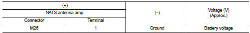
Is the inspection result normal? YES >> GO TO 6.
NO >> GO TO 5.
5.CHECK NATS ANTENNA AMP. POWER SUPPLY CIRCUIT
1. Disconnect IPDM E/R connector.
2. Check continuity between IPDM E/R harness connector and NATS antenna amp. connector.
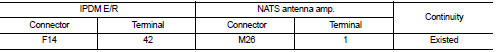
3. Check continuity between IPDM E/R harness connector and ground.
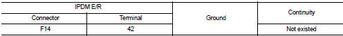
Is the inspection result normal? YES >> Replace IPDM E/R. Refer to PCS-63, "Removal and Installation".
NO >> Repair or replace harness.
6.CHECK NATS ANTENNA AMP. GROUND CIRCUIT
Check continuity between NATS antenna amp. harness connector and ground.
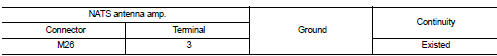
Is the inspection result normal? YES >> GO TO 7.
NO >> Repair or replace harness.
7.CHECK NATS ANTENNA AMP. SIGNAL
1. Connect BCM connector and NATS antenna amp. connector.
2. Check voltage between BCM harness connector and ground.
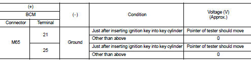
Is the inspection result normal? YES >> GO TO 9.
NO >> GO TO 8.
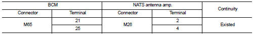
8.CHECK NATS ANTENNA AMP. SIGNAL CIRCUIT
1. Disconnect NATS antenna amp. connector.
2. Check continuity between BCM harness connector and NATS antenna amp. harness connector.
3. Check continuity between BCM harness connector and ground.
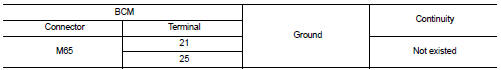
Is the inspection result normal? YES >> Replace NATS antenna amp. Refer to SEC-233, "Removal and Installation".
NO >> Repair or replace harness.
9.CHECK INTERMITTENT INCIDENT
Refer to GI-42, "Intermittent Incident".
>> INSPECTION END
 P1616 ECM
DTC Logic
DTC DETECTION LOGIC
DTC CONFIRMATION PROCEDURE
1.PERFORM DTC CONFIRMATION PROCEDURE FOR MALFUNCTION
1. Turn ignition switch ON amd wait 2 seconds or more.
2. Check DTC in “Self Diag ...
 B2191 difference of key
DTC Logic
DTC DETECTION LOGIC
DTC CONFIRMATION PROCEDURE
1.PERFORM DTC CONFIRMATION PROCEDURE
1. Turn ignition switch ON.
2. Check DTC in “Self Diagnostic Result” mode of “BCM” using CO ...
Other materials:
Diagnosis and repair work flow
Work Flow
DETAILED FLOW
1.INTERVIEW FROM THE CUSTOMER
Clarify customer complaints before inspection. First of all, perform an
interview utilizing DLN-37, "Diagnostic
Work Sheet" and reproduce symptoms as well as fully understand it. Ask customer
about his/her complaints
carefully. ...
Diagnosis system [ABS actuator and electric unit (control
unit)]
CONSULT-III Function
APPLICATION ITEMS
CONSULT-III can display each diagnostic item using the diagnostic test modes
as follows.
*1: The following diagnosis information is erased by erasing.
• DTC
• Freeze frame data (FFD)
*2: Although “Function Test” is selectable, do not use its.
...
Vehicle loading information
WARNING
It is extremely dangerous to ride in the cargo area inside the vehicle.
In the event of a collision, individuals positioned in these unsecured areas are significantly more likely to suffer serious injury or fatalities.
Never allow passengers to ...
