Nissan Juke Service and Repair Manual : Hood switch
Component Function Check
1.CHECK FUNCTION
1. Select ŌĆ£HOOD SWŌĆØ in ŌĆ£Data MonitorŌĆØ mode of ŌĆ£IPDM E/RŌĆØ using CONSULT-III.
2. Check ŌĆ£HOOD SWŌĆØ indication under the following condition.
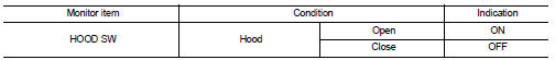
Is the indication normal? YES >> Hood switch is OK.
NO >> Go to SEC-155, "Diagnosis Procedure".
Diagnosis Procedure
1.CHECK HOOD SWITCH SIGNAL CIRCUIT 1
1. Turn ignition switch OFF.
2. Disconnect hood switch connector.
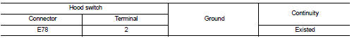
3. Check voltage between hood switch harness connector and ground.
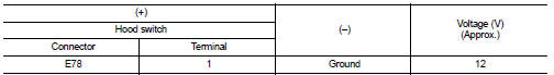
Is the inspection result normal? YES >> GO TO 3.
NO >> GO TO 2.
2.CHECK HOOD SWITCH SIGNAL CIRCUIT 2
1. Disconnect IPDM E/R connector.
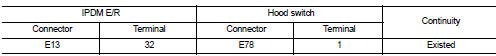
2. Check continuity between IPDM E/R harness connector and hood switch harness connector
3. Check continuity between IPDM E/R harness connector and ground.
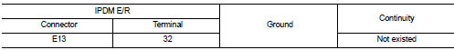
Is the inspection result normal? YES >> Replace IPDM E/R. Refer to PCS-34, "Removal and Installation".
NO >> Repair or replace harness.
3.CHECK HOOD SWITCH GROUND CIRCUIT
Check continuity between hood switch harness connector and ground.
Is the inspection result normal? YES >> GO TO 4.
NO >> Repair or replace harness.
4.CHECK HOOD SWITCH
Refer to SEC-156, "Component Inspection".
Is the inspection result normal? YES >> GO TO 5.
NO >> Replace hood switch.
5.CHECK INTERMITTENT INCIDENT
Refer to GI-42, "Intermittent Incident".
>> INSPECTION END
Component Inspection
1.CHECK HOOD SWITCH
1. Turn ignition switch OFF.
2. Disconnect hood switch connector.
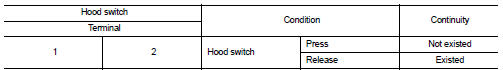
3. Check continuity between hood switch terminals
Is the inspection result normal? YES >> INSPECTION END
NO >> Replace hood switch.
 B2110 shift position/clutch interlock switch
DTC Logic
DTC DETECTION LOGIC
NOTE:
If DTC B2110 is displayed with DTC U1000, first perform the trouble diagnosis
for DTC U1000. Refer to PCS-
30, "DTC Logic".
DTC CONFIRMATION PROC ...
 Horn function
Component Function Check
1.CHECK FUNCTION 1
1. Disconnect vehicle security horn relay.
2. Perform ŌĆ£VEHICLE SECURITY HORNŌĆØ in ŌĆ£ACTIVE TESTŌĆØ mode of ŌĆ£THEFT ALMŌĆØ of ŌĆ£BCMŌĆØ
using CONSU ...
Other materials:
Refilling
1. Remove filler plug (1). Fill with new gear oil until oil level reaches
the specified level near filler plug mounting hole
Oil grade and viscosity : Refer to MA-13, "Fluids
and Lubricants".
Oil capacity : Refer to DLN-167, "General
Specification".
2. After refilling oil, ...
P0327, P0328 KS
DTC Logic
DTC DETECTION LOGIC
DTC CONFIRMATION PROCEDURE
1.PRECONDITIONING
If DTC Confirmation Procedure has been previously conducted, always turn
ignition switch OFF and wait at
least 10 seconds before conducting the next test.
TESTING CONDITION:
Before performing the following proced ...
P173C 2GR incorrect ratio
DTC Logic
DTC DETECTION LOGIC
DTC CONFIRMATION PROCEDURE
CAUTION:
ŌĆó Be sure to perform ŌĆ£TM-447, "Diagnosis Procedure"ŌĆØ and then perform ŌĆ£DTC
CONFIRMATION PROCEDUREŌĆØ.
ŌĆó Never perform "DTC CONFIRMATION PROCEDURE" before the repairs. Doing so may
result in a s ...
