Nissan Juke Service and Repair Manual : B210C starter control relay
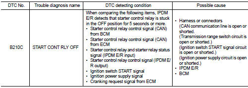
DTC Logic
DTC DETECTION LOGIC
NOTE
:
• If DTC B210C is displayed with DTC U1000, first perform the trouble diagnosis
for DTC U1000. Refer to
PCS-30, "DTC Logic".
• When IPDM E/R power supply voltage is low (Approx. 7 - 8 V for about 1 second), the DTC B210C may be detected.
DTC CONFIRMATION PROCEDURE
1.PERFORM DTC CONFIRMATION PROCEDURE 1
1. Press push-button ignition switch under the following conditions to start engine, and wait 5 seconds or more.
- Selector lever: In the P position - Brake pedal: Depressed 2. Check DTC in “Self Diagnostic Result” mode of “IPDM E/R” using CONSULT-III.
Is DTC detected? YES >> Go to SEC-215, "Diagnosis Procedure".
NO >> GO TO 2.
2.PERFORM DTC CONFIRMATION PROCEDURE 2
1. Stop engine.
2. Perform DTC CONFIRMATION PROCEDURE for DTC P1650. Refer to EC-366, "DTC Logic" (MR16DDT) or EC-725, "DTC Logic" (HR16DE).
3. Turn ignition switch ON.
4. Check DTC in “Self Diagnostic Result” mode of “IPDM E/R” using CONSULT-III.
Is DTC detected? YES >> Refer to SEC-215, "Diagnosis Procedure".
NO >> INSPECTION END
Diagnosis Procedure
1.INSPECTION START
Perform inspection in accordance with procedure that confirms DTC.
Which procedure confirms DTC? DTC confirmation procedure 1>>GO TO 2.
DTC confirmation procedure 2>>GO TO 7.
2.CHECK DTC OF BCM
Check DTC in “Self Diagnostic Result” mode of “BCM” using CONSULT-III.
Is DTC detected? YES >> Perform the trouble diagnosis related to the detected DTC. Refer to BCS-67, "DTC Index".
NO >> GO TO 3.
3.CHECK DTC OF TCM
Check DTC in “Self Diagnostic Result” mode of “TRANSMISSION” using CONSULT-III.
Is DTC detected? YES >> Perform the trouble diagnosis related to the detected DTC. Refer to TM-171, "DTC Index" (CVT: RE0F10B) or TM-366, "DTC Index" (CVT: RE0F11A).
NO >> GO TO 4.
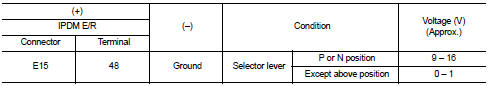
4.CHECK TRANSMISSION RANGE SWITCH SIGNAL
1. Turn ignition switch ON.
2. Check voltage between IPDM E/R harness connector and ground.
Is the inspection result normal? YES >> GO TO 5.
NO >> Repair or replace harness. Refer to STR-12, "CVT : Wiring Diagram".
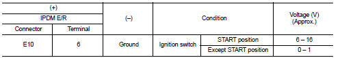
5.CHECK IGNITION SWITCH START SIGNAL
1. Turn ignition switch OFF.
2. Disconnect IPDM E/R harness connector.
3. Check voltage between IPDM E/R harness connector and ground.
Is the inspection result normal? YES >> GO TO 6.
NO >> Repair or replace harness. Refer to STR-12, "CVT : Wiring Diagram".
6.PERFORM DTC CONFIRMATION PROCEDURE AGAIN
1. Reconnect IPDM E/R harness connector.
2. Turn ignition switch ON.
3. Select “Self Diagnostic Result” mode of “IPDM E/R” using CONSULT-III.
4. Touch “ERASE”.
5. Perform DTC CONFIRMATION PROCEDURE for DTC B210C. Refer to SEC-215, "DTC Logic".
Is DTC detected? YES >> Replace IPDM E/R. Refer to PCS-63, "Removal and Installation".
NO >> INSPECTION END
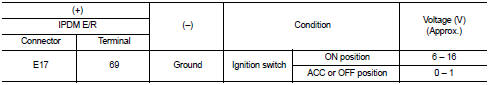
7.CHECK IGNITION POWER SUPPLY SIGNAL
1. Turn ignition switch OFF.
2. Disconnect IPDM E/R harness connector.
3. Check voltage between IPDM E/R harness connector and ground.
Is the inspection result normal? YES >> Replace IPDM E/R. Refer to PCS-63, "Removal and Installation".
NO >> Repair or replace harness. Refer to STR-12, "CVT : Wiring Diagram".
 B210B starter control relay
DTC Logic
DTC DETECTION LOGIC
NOTE:
If DTC B210B is displayed with DTC U1000, first perform the trouble diagnosis
for DTC U1000. Refer to PCS-
30, "DTC Logic".
DTC CONFIRMATION PROC ...
 B210D starter relay
DTC Logic
DTC DETECTION LOGIC
NOTE:
• If DTC B210D is displayed with DTC U1000, first perform the trouble diagnosis
for DTC U1000. Refer to
PCS-59, "DTC Logic".
• If DTC B210D is ...
Other materials:
Diagnosis system (BCM) (with intelligent key system)
Common item
COMMON ITEM : CONSULT-III Function (BCM - COMMON ITEM)
APPLICATION ITEM
CONSULT-III performs the following functions via CAN communication with BCM.
SYSTEM APPLICATION
BCM can perform the following functions for each system.
NOTE:
It can perform the diagnosis modes except the ...
Washer tank
Exploded View
1. Front washer nozzle LH
2. Front washer nozzle RH
3. Front washer tube LH
4. Front washer tube RH
5. Check valve
6. Front washer tube
7. Joint
8. Washer tank inlet cap
9. Washer tank inlet
10. Washer tank
11. Headlamp washer pump
12. Washer pump
13. Packing
1 ...
Windows
POWER WINDOWS
WARNING
• Make sure that all passengers have their hands, etc. inside the vehicle
while it is in motion and before closing the windows. Use the window lock switch
to prevent unexpected use of the power windows.
• Do not leave children unattended inside the vehicle. They coul ...
