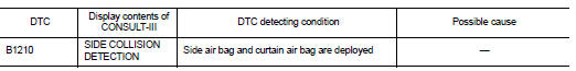
Nissan Juke Service and Repair Manual : B1210 side collision detection
Description
The side air bag and curtain air bag are activated by the air bag diagnosis sensor unit signal transmitted at the time of side collision.
DTC Logic
DTC DETECTION LOGIC
DTC CONFIRMATION PROCEDURE
1.CHECK SELF-DIAG RESULT
 With CONSULT-III
1. Turn ignition switch ON.
2. Perform “Self Diagnostic Result” mode of “AIR BAG” using CONSULT-III.
 Without CONSULT-III
1. Turn ignition switch ON.
2. Check the air bag warning lamp status. Refer to SRC-12, "On Board Diagnosis Function".
NOTE
:
SRS does not enter the diagnosis mode if no malfunction is detected in the user
mode.
Is malfunctioning part detected? YES >> Refer to SRC-141, "Diagnosis Procedure".
NO >> INSPECTION END
Diagnosis Procedure
WARNING:
• Before servicing, turn ignition switch OFF, disconnect battery negative
terminal, and wait at least 3
minutes or more. (To discharge backup capacitor.)
• Never use unspecified tester or other measuring device.
1.PERFORM COLLISION DIAGNOSIS
Perform collision diagnosis.Refer to SR-8, "FOR SIDE AND ROLLOVER COLLISION : When SRS is activated in a collision" or SR-9, "FOR SIDE AND ROLLOVER COLLISION : When SRS is not activated in a collision".
Is collision diagnosis complete? YES >> GO TO 2.
NO >> INSPECTION END
2.FINAL INSPECTION
Perform “AIR BAG” Self Diagnostic Result.
Is the inspection result normal? YES >> INSPECTION END
NO >> Perform diagnosis of applicable DTC.Refer to SRC-18, "DTC Index".
 B1209 frontal collision detection
Description
The air bags and seat belt pre-tensioners for driver and passenger are
activated by the air bag diagnosis sensor
unit signal transmitted at the time of the frontal collision.
DTC Logi ...
 B1212, B1213, B1214 satellite sensor RH
DTC Logic
DTC DETECTION LOGIC
DTC CONFIRMATION PROCEDURE
1.CHECK SELF-DIAG RESULT
With CONSULT-III
1. Turn ignition switch ON.
2. Perform “Self Diagnostic Result” mode of “AIR BAG” usi ...
Other materials:
Warning lights
All-Wheel Drive (AWD) warning light
(AWD model)
When the ignition switch is in the “ON” position, the All-Wheel Drive (AWD) warning
light will illuminate. It will turn off soon after the engine is started.
If the AWD system malfunctions or the revolution or radius of the front and the
r ...
Basic inspection
DIAGNOSIS AND REPAIR WORKFLOW
Work Flow
DETAILED FLOW
1.INTERVIEW FROM THE CUSTOMER
Clarify customer complaints before inspection. First of all, perform an
interview utilizing STC-17, "Diagnostic
Work Sheet" and reproduce symptoms as well as fully understand it. Ask customer
about ...
Component parts
Component Parts Location
LHD models
1. ABS actuator and electric unit (control
unit)
Refer to BRC-97, "Component Parts
Location".
2. ECM
Refer to EC-25, "ENGINE CONTROL
SYSTEM :
Component Parts Location".
3. Front wheel sensor
Refer to BRC-97, "Component Parts
...
