Nissan Juke Service and Repair Manual : B210D starter relay
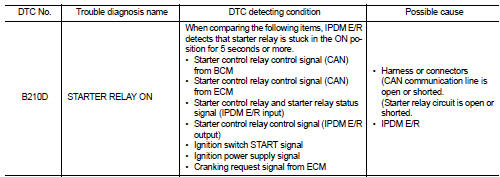
DTC Logic
DTC DETECTION LOGIC
NOTE
:
ŌĆó If DTC B210D is displayed with DTC U1000, first perform the trouble diagnosis
for DTC U1000. Refer to
PCS-59, "DTC Logic".
ŌĆó If DTC B210D is displayed with DTC B209F, first perform the trouble diagnosis for DTC B209F. Refer to SEC-209, "DTC Logic".
ŌĆó If DTC B210D is displayed with DTC B20A0, first perform the trouble diagnosis for DTC B20A0. Refer to SEC-211, "DTC Logic".
DTC CONFIRMATION PROCEDURE
1.PERFORM DTC CONFIRMATION PROCEDURE
1. Press push-button ignition switch under the following conditions to start engine, and wait 5 seconds or more.
- Selector lever: In the P position - Brake pedal: Depressed 2. Check DTC in ŌĆ£Self Diagnostic ResultŌĆØ mode of ŌĆ£IPDM E/RŌĆØ using CONSULT-III.
Is DTC detected? YES >> Go to SEC-218, "Diagnosis Procedure".
NO >> GO TO 2.
2.PERFORM DTC CONFIRMATION PROCEDURE 2
1. Stop engine.
2. Perform DTC CONFIRMATION PROCEDURE for DTC P1650. Refer to EC-366, "DTC Logic" (MR16DDT) or EC-725, "DTC Logic" (HR16DE).
3. Turn ignition switch ON.
4. Check DTC in ŌĆ£Self Diagnostic ResultŌĆØ mode of ŌĆ£IPDM E/RŌĆØ using CONSULT-III.
Is DTC detected? YES >> Refer to SEC-218, "Diagnosis Procedure".
NO >> INSPECTION END
Diagnosis Procedure
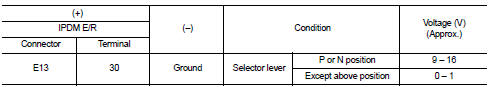
1.CHECK STARTER RELAY CONTROL SIGNAL
1. Turn ignition switch ON.
2. Check voltage between IPDM E/R harness connector and ground.
Is the inspection result normal? YES >> GO TO 4.
NO >> GO TO 2.
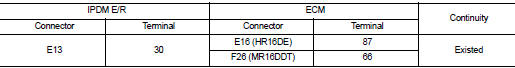
2.CHECK CRANKING REQUEST SIGNAL CIRCUIT
1. Turn ignition switch OFF.
2. Disconnect IPDM E/R connector.
3. Disconnect ECM connector.
4. Check continuity between IPDM E/R harness connector and ECM harness connector.
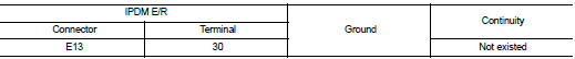
5. Check continuity between BCM harness connector and ground.
Is the inspection result normal? YES >> GO TO 3.
NO >> Repair or replace harness.
3.REPLACE ECM
Replace ECM.
Refer to EC-447, "Removal and Installation" (MR16DDT) or EC-805, "Removal and Installation" (HR16DE).
>> INSPECTION END
4.PERFORM DTC CONFIRMATION PROCEDURE AGAIN
1. Turn ignition switch ON.
2. Select ŌĆ£Self Diagnostic ResultŌĆØ mode of ŌĆ£IPDM E/RŌĆØ using CONSULT-III.
3. Touch ŌĆ£ERASEŌĆØ.
4. Perform DTC CONFIRMATION PROCEDURE for DTC B210D. Refer to SEC-218, "DTC Logic".
Is DTC detected? YES >> Replace IPDM E/R. Refer to PCS-34, "Removal and Installation".
NO >> INSPECTION END
 B210C starter control relay
DTC Logic
DTC DETECTION LOGIC
NOTE:
ŌĆó If DTC B210C is displayed with DTC U1000, first perform the trouble diagnosis
for DTC U1000. Refer to
PCS-30, "DTC Logic".
ŌĆó When IPDM E/R po ...
 B210E starter relay
DTC Logic
DTC DETECTION LOGIC
NOTE:
ŌĆó If DTC B210E is displayed with DTC U1000, first perform the trouble diagnosis
for DTC U1000. Refer to
PCS-59, "DTC Logic".
ŌĆó If DTC B210E is ...
Other materials:
Periodic maintenance
STEERING WHEEL
Inspection
STEERING WHEEL AXIAL END PLAY
1. Check installation conditions of steering gear assembly, front suspension
assembly, axle and steering column
assembly.
2. Check if movement exists when steering wheel is moved up and down, to the
left and right and to the axial
dir ...
Information display (speed limiter)
Component Function Check
1.CHECK INFORMATION DISPLAY (SPEED LIMITER) FUNCTION
1. Start engine.
2. Press speed limiter MAIN switch.
3. Drive the vehicle at more than 30 km/h (20 MPH).
CAUTION:
Always drive vehicle at a safe speed.
4. Press SET/− switch.
5. Perform a test drive on a fl ...
Battery
ŌĆó Keep the battery surface clean and dry.
Clean the battery with a solution of baking soda and water.
ŌĆó Make certain the terminal connections are clean and securely tightened.
ŌĆó If the vehicle is not to be used for 30 days or longer, disconnect the negative
battery terminal cable to ...
