Nissan Juke Service and Repair Manual : B2110 shift position/clutch interlock switch
DTC Logic
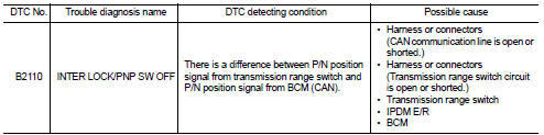
DTC DETECTION LOGIC
NOTE
:
If DTC B2110 is displayed with DTC U1000, first perform the trouble diagnosis
for DTC U1000. Refer to PCS-
30, "DTC Logic".
DTC CONFIRMATION PROCEDURE
1.PERFORM DTC CONFIRMATION PROCEDURE
1. Shift selector lever to the P position.
2. Turn ignition switch ON and wait 1 second or more.
3. Shift selector lever to the N position and wait 1 second or more.
4. Shift selector lever to any position other than P and N, and wait 1 second or more.
5. Check DTC in ÔÇťSelf Diagnostic ResultÔÇŁ mode of ÔÇťIPDM E/RÔÇŁ using CONSULT-III.
Is DTC detected? YES >> Go to SEC-153, "Diagnosis Procedure".
NO >> INSPECTION END
Diagnosis Procedure
1.CHECK DTC OF BCM
Check DTC in ÔÇťSelf Diagnostic ResultÔÇŁ mode of ÔÇťBCMÔÇŁ using CONSULT-III.
Is DTC detected? YES >> Perform the trouble diagnosis related to the detected DTC. Refer to BCS-67, "DTC Index".
NO >> GO TO 2.
2.CHECK DTC OF TCM
Check DTC in ÔÇťSelf Diagnostic ResultÔÇŁ mode of ÔÇťTCMÔÇŁ using CONSULT-III.
Is DTC detected? YES >> Perform the trouble diagnosis related to the detected DTC. Refer to TM-171, "DTC Index" (CVT: RE0F10B) or TM-366, "DTC Index" (CVT: RE0F11A).
NO >> GO TO 3.
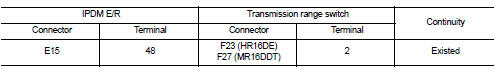
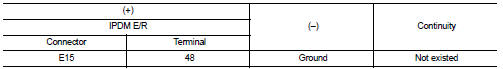
3.CHECK IPDM E/R SIGNAL CIRCUIT OPEN AND SHORT
1. Turn ignition switch OFF.
2. Disconnect IPDM E/R connector.
3. Disconnect transmission range swiwtch connector.
4. Check continuity between IPDM E/R harness connector and transmission range swiwtch harness connector
5. Check continuity between IPDM E/R harness connector and ground.
Is the inspection result normal? YES >> Replace IPDM E/R. Refer to PCS-34, "Removal and Installation".
NO >> Repair or replace harness.
 B210F shift position/clutch interlock switch
DTC Logic
DTC DETECTION LOGIC
NOTE:
If DTC B210F is displayed with DTC U1000, first perform the trouble diagnosis
for DTC U1000. Refer to PCS-
30, "DTC Logic".
DTC CONFIRMATION PROC ...
 Hood switch
Component Function Check
1.CHECK FUNCTION
1. Select ÔÇťHOOD SWÔÇŁ in ÔÇťData MonitorÔÇŁ mode of ÔÇťIPDM E/RÔÇŁ using CONSULT-III.
2. Check ÔÇťHOOD SWÔÇŁ indication under the following condition.
...
Other materials:
B1178 lap Pre-tensioner RH
DTC Logic
DTC CONFIRMATION PROCEDURE
1.CHECK SELF-DIAGNOSTIC RESULT
With CONSULT-III
1. Turn ignition switch ON.
2. Perform ÔÇťSelf Diagnostic ResultÔÇŁ mode of ÔÇťAIR BAGÔÇŁ using CONSULT-III.
Without CONSULT-III
1. Turn ignition switch ON.
2. Check the air bag warning lamp status. Refe ...
Basic inspection
DIAGNOSIS AND REPAIR WORK FLOW
Work Flow
DESCRIPTION OF TROUBLE DIAGNOSIS FLOWCHART
DETAILS OF TROUBLE DIAGNOSIS FLOWCHART
1.OBTAIN INFORMATION ABOUT SYMPTOM
Interview the customer to obtain as much information as possible about the
conditions and environment under
which the malfunction oc ...
AEB with Pedestrian Detection system limitations
WARNING
The following section details the inherent operational limitations of the Automatic Emergency Braking (AEB) with Pedestrian Detection system. Failure to remain fully engaged as the driver and to operate your Nissan Leaf in strict accordance with these limitations could result in a colli ...
