Nissan Juke Service and Repair Manual : Basic inspection
DIAGNOSIS AND REPAIR WORK FLOW
Work Flow
DESCRIPTION OF TROUBLE DIAGNOSIS FLOWCHART
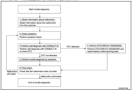
DETAILS OF TROUBLE DIAGNOSIS FLOWCHART
1.OBTAIN INFORMATION ABOUT SYMPTOM
Interview the customer to obtain as much information as possible about the conditions and environment under which the malfunction occurs.
>> GO TO 2.
2.CHECK SYMPTOM
• Check the symptom based on the information obtained from the customer.
• Check if any other malfunctions are present.
>> GO TO 3.
3.CONSULT-III SELF-DIAGNOSIS
Perform “MULTI DISPLAY” “self diagnosis” by connecting CONSULT-III.
NOTE
:
If “CAN COM CIRC [U1000]” is displayed, start the diagnosis from the CAN
communication system. AV-116,
"Diagnosis Procedure".
Is any DTC No. displayed? YES >> GO TO 4.
NO >> GO TO 5.
4.DTC/SYSTEM DIAGNOSIS
Perform a DTC/system diagnosis and repair or replace any malfunctioning part.
>> GO TO 6.
5.PERFORM DIAGNOSIS BY SYMPTOM
Perform a diagnosis by symptom and repair or replace any malfunctioning part.
>> GO TO 6.
6.FINAL CHECK
Check that the multi display unit functions normally.
Does it operate normally? YES >> End of trouble diagnosis NO >> GO TO 2.
 Wiring diagram
NISSAN DYNAMIC CONTROL SYSTEM
Wiring Diagram
For connector terminal arrangements, harness layouts, and alphabets in a
(option abbreviation; if not
described in wiring diagram), refer to GI-12, &qu ...
 Removal and installation
MULTI DISPLAY UNIT
Exploded View
REMOVAL
Refer to IP-12, "Exploded View".
DISASSEMBLY
1. Silencer tape
2. Multi display unit
3. Silencer tape
4. Clip
5. Control finisher
Rem ...
Other materials:
Diagnosis system (navi control unit)
Diagnosis Description
On-Board Diagnosis Item
• On-board diagnosis is performed in service test mode.
• On-board diagnosis checks if the system operates normally.
Service test mode
METHOD OF STARTING
1. Start the engine.
2. Turn OFF audio.
3. While pressing the “SET UP” switch, ...
Additional service when replacing TCM
Description
Always perform the following items when the TCM is replaced.
CHECK LOADING OF CALIBRATION DATA
• The TCM acquires calibration data (individual characteristic value) of each
solenoid that is stored in the
ROM assembly (in the control valve). This enables the TCM to perform accurat ...
Avoiding collision and rollover
WARNING
Failure to operate this vehicle in a safe and prudent manner may result in
loss of control or an accident.
Be alert and drive defensively at all times. Obey all traffic regulations. Avoid
excessive speed, high speed cornering, or sudden steering maneuvers, because these
driving pract ...
