Nissan Juke Service and Repair Manual : Wiring diagram
NISSAN DYNAMIC CONTROL SYSTEM
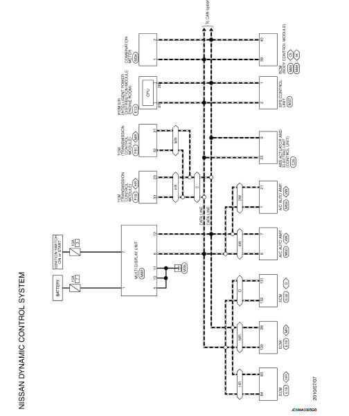
Wiring Diagram
For connector terminal arrangements, harness layouts, and alphabets in a
 (option abbreviation; if not
described in wiring diagram), refer to GI-12, "Connector Information/Explanation
of Option Abbreviation".
 Ecu diagnosis information
MULTI DISPLAY UNIT
List of ECU Reference
...
 Basic inspection
DIAGNOSIS AND REPAIR WORK FLOW
Work Flow
DESCRIPTION OF TROUBLE DIAGNOSIS FLOWCHART
DETAILS OF TROUBLE DIAGNOSIS FLOWCHART
1.OBTAIN INFORMATION ABOUT SYMPTOM
Interview the customer to obtain as ...
Other materials:
B26F6 BCM
DTC Logic
DTC DETECTION LOGIC
NOTE:
• If DTC B26F6 is displayed with DTC U1000, first perform the trouble diagnosis
for DTC U1000. Refer to
BCS-83, "DTC Logic".
• If DTC B26F6 is displayed with DTC U1010, first perform the trouble diagnosis
for DTC U1010. Refer to
BCS-84, &qu ...
Blower fan resistor
Exploded View
1. Heater unit assembly
2. Fan control amp.*1
3. Blower fan resistor*2
4. Blower motor
5. Blower motor cover
• *1: Automatic air conditioner
• *2: Manual air conditioner or Manual heater
Removal and Installation
REMOVAL
1. Remove instrument panel assembly. Refer to I ...
A/C auto AMP.
Reference Value
CONSULT-III DATA MONITOR REFERENCE VALUES
*: “DUTY” is displayed, but voltage is indicated. Or unit is not displayed
but unit is (V).
TERMINAL LAYOUT
PHYSICAL VALUES
*: With K9K
Fail-safe
FAIL-SAFE FUNCTION
If a communication error exists between the A/C auto am ...
