Nissan Juke Service and Repair Manual : Diagnosis and repair workflow
Work Flow
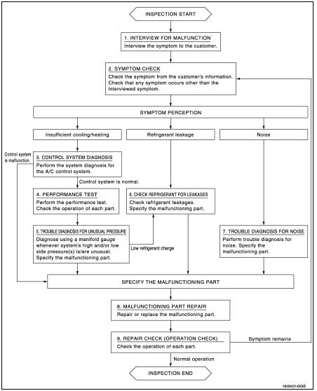
OVERALL SEQUENCE
DETAILED FLOW
1.INTERVIEW FOR MALFUNCTION
Interview the symptom to the customer.
>> GO TO 2.
2.SYMPTOM CHECK
Check the symptom from the customer's information. Check that any symptom occurs other than the interviewed symptom.
Insufficient cooling/heating>>GO TO 3.
Refrigerant leakage>>GO TO 6.
Noise >> GO TO 7.
3.CONTROL SYSTEM DIAGNOSIS
Perform the system diagnosis for the A/C control system.
• Refer to HAC-44, "Work Flow". (AUTOMATIC AIR CONDITIONING: 4WD models) • Refer to HAC-135, "Work Flow". (AUTOMATIC AIR CONDITIONING: 2WD models) • Refer to HAC-216, "Work Flow". (MANUAL AIR CONDITIONING: 4WD models) • Refer to HAC-271, "Work Flow". (MANUAL AIR CONDITIONING: 2WD models)
Is A/C control system normal? YES >> GO TO 4.
NO >> GO TO 8.
4.PERFORMANCE TEST
Perform the performance test. Check the operation of each part. Refer to HA-81, "Inspection".
>> GO TO 5.
5.TROUBLE DIAGNOSIS FOR UNUSUAL PRESSURE
Diagnose using a manifold gauge whenever system's high and/or low side pressure(s) is/are unusual. Specify the malfunctioning part. Refer to HA-83, "Symptom Table".
Low refrigerant charge>>GO TO 6.
Except above>>GO TO 8.
6.CHECK REFRIGERANT FOR LEAKAGES
Check refrigerant for leakages. Specify the malfunctioning part. Refer to HA-74, "Leak Test".
>> GO TO 8.
7.TROUBLE DIAGNOSIS FOR NOISE
Perform trouble diagnosis for noise. Specify the malfunctioning part. Refer to HA-85, "Symptom Table".
>> GO TO 8.
8.MALFUNCTION PART REPAIR
Repair or replace the malfunctioning part.
>> GO TO 9.
9.REPAIR CHECK (OPERATION CHECK)
Check the operation of each part.
Does it operate normally? YES >> INSPECTION END
NO >> GO TO 2.
 Basic inspection
...
 Refrigerant
Description
CONNECTION OF SERVICE TOOLS AND EQUIPMENT
1. Shut-off valve
2. A/C service valve
3. Recovery/recycling/recharging
equipment
4. Vacuum pump
5. Manifold gauge set
6. Refrigeran ...
Other materials:
Tire pressure
Tire Pressure Monitoring System (TPMS)
WARNING
Radio frequency signals emitted by the TPMS may potentially interfere with sensitive electric medical equipment. Individuals who rely on a pacemaker or other implantable medical devices should consult with the equipment manufacturer regarding ...
Precaution for Supplemental Restraint System (SRS) "AIR BAG" and "SEAT BELT
PRE-TENSIONER"
The Supplemental Restraint System such as “AIR BAG” and “SEAT BELT PRE-TENSIONER”,
used along
with a front seat belt, helps to reduce the risk or severity of injury to the
driver and front passenger for certain
types of collision. Information necessary to service the system safely is
...
P1572 ASCD brake switch
DTC Logic
DTC DETECTION LOGIC
NOTE:
• If DTC P1572 is displayed with DTC P0605, first perform the trouble diagnosis
for DTC P0605. Refer
to EC-302, "DTC Logic".
• This self-diagnosis has the one trip detection logic. When malfunction A is
detected, DTC is not
stored in ECM me ...
