Nissan Juke Service and Repair Manual : Horn function
Component Function Check
1.CHECK FUNCTION 1
1. Disconnect vehicle security horn relay.
2. Perform “VEHICLE SECURITY HORN” in “ACTIVE TEST” mode of “THEFT ALM” of “BCM” using CONSULT- III.
3. Check the horn operation.

Is the operation normal? YES >> GO TO 2.
NO >> Go to SEC-157, "Diagnosis Procedure".
2.CHECK FUNCTION 2
1. Reconnect vehicle security horn relay.
2. Disconnect horn relay.
3. Perform “VEHICLE SECURITY HORN” in “ACTIVE TEST” mode of “THEFT ALM” of “BCM” using CONSULT- III.
4. Check the horn operation.

Is the operation normal? YES >> INSPECTION END
NO >> Go to SEC-157, "Diagnosis Procedure".
Diagnosis Procedure
1.INSPECTION START
Perform inspection in accordance with procedure that confirms malfunction.
Which procedure confirms malfunction? Component Function Check 1>>GO TO 2.
Component Function Check 2>>GO TO 4.
2.CHECK HORN FUNCTION
Check that horn functions properly using horn switch.
Do horns sound? YES >> GO TO 3.
NO >> Check horn circuit. Refer to HRN-3, "Wiring Diagram".
3.CHECK HORN CONTROL CIRCUIT
1. Disconnect horn relay.
2. Disconnect IPDM E/R connector.
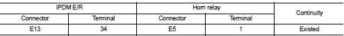
3. Check continuity between IPDM E/R harness connector and horn relay harness connector.
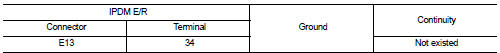
4. Check continuity between IPDM E/R harness connector and ground.
Is the inspection result normal? YES >> GO TO 6.
NO >> Repair or replace harness.
4.CHECK HORN FUNCTION
Check that vehicle security horn functions properly using horn switch.
Do horns sound? YES >> GO TO 5.
NO >> Check vehicle security horn circuit. Refer to HRN-3, "Wiring Diagram".
5.CHECK VEHICLE SECURITY HORN CONTROL CIRCUIT
1. Disconnect IPDM E/R connector.
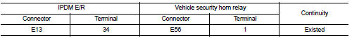
2. Check continuity between IPDM E/R harness connector and vehicle security horn relay harness connector.
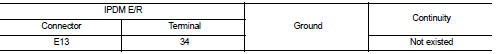
3. Check continuity between IPDM E/R harness connector and ground.
Is the inspection result normal? YES >> GO TO 6.
NO >> Repair or replace harness.
6.CHECK INTERMITTENT INCIDENT
Refer to GI-42, "Intermittent Incident".
>> INSPECTION END
 Hood switch
Component Function Check
1.CHECK FUNCTION
1. Select “HOOD SW” in “Data Monitor” mode of “IPDM E/R” using CONSULT-III.
2. Check “HOOD SW” indication under the following condition.
...
 Security indicator lamp
Component Function Check
1.CHECK FUNCTION
1. Perform “THEFT IND” in “ACTIVE TEST” mode of “IMMU” of “BCM” using
CONSULT-III.
2. Check security indicator lamp operation.
Is the ...
Other materials:
Key reminder function does not operate
Diagnosis Procedure
1.CHECK DTC WITH BCM
Check that DTC is not detected with BCM.
Is the inspection result normal?
YES >> GO TO 2.
NO >> Refer to BCS-67, "DTC Index".
2.CHECK “ANTI KEY LOCK IN FUNCTI” SETTING IN “WORK SUPPORT”
1. Select “INTELLIGENT KEY†...
P range interlock door lock/unlock function does not operate
Diagnosis Procedure
1.CHECK “AUTOMATIC LOCK/UNLOCK SELECT” SETTING IN “WORK SUPPORT”
1. Select “DOOR LOCK” of “BCM” using CONSULT-III.
2. Select “AUTOMATIC LOCK/UNLOCK SELECT” in “WORK SUPPORT” mode.
3. Check “AUTOMATIC LOCK/UNLOCK SELECT” setting in “WORK SUPPORT†...
Tire pressure
Tire Pressure Monitoring System (TPMS)
WARNING
Radio frequency signals emitted by the TPMS may potentially interfere with sensitive electric medical equipment. Individuals who rely on a pacemaker or other implantable medical devices should consult with the equipment manufacturer regarding ...
