Nissan Juke Service and Repair Manual : Security indicator lamp
Component Function Check
1.CHECK FUNCTION
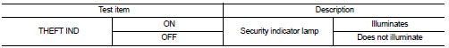
1. Perform ÔÇťTHEFT INDÔÇŁ in ÔÇťACTIVE TESTÔÇŁ mode of ÔÇťIMMUÔÇŁ of ÔÇťBCMÔÇŁ using CONSULT-III.
2. Check security indicator lamp operation.
Is the inspection result normal? YES >> INSPECTION END
NO >> Go to SEC-159, "Diagnosis Procedure".
Diagnosis Procedure
1.CHECK SECURITY INDICATOR LAMP POWER SUPPLY CIRCUIT
1. Turn ignition switch OFF.
2. Disconnect combination meter connector.
3. Check voltage between combination meter harness connector and ground.
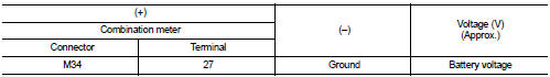
Is the inspection result normal? YES >> GO TO 2.
NO-1 >> Check 10 A fuse [No. 11, located in the fuse block (J/B)].
NO-2 >> Check harness for open or short between combination meter and fuse.
2.CHECK SECURITY INDICATOR LAMP SIGNAL
1. Connect combination meter connector.
2. Disconnect BCM connector.
3. Check voltage between BCM harness connector and ground.
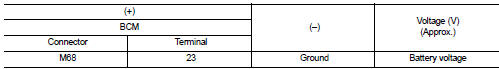
Is the inspection result normal? YES >> GO TO 3.
NO >> GO TO 4.
3.REPLACE BCM
1. Replace BCM. Refer to BCS-93, "Removal and Installation".
2. Perform initialization of BCM and registration of all Intelligent Keys using CONSULT-III.
For initialization and registration procedures, refer to CONSULT-III Operation Manual NATS-IVIS/NVIS.
>> INSPECTION END
4.CHECK SECURITY INDICATOR LAMP CIRCUIT
1. Disconnect combination meter connector.
2. Check continuity between combination meter harness connector and BCM harness connector.
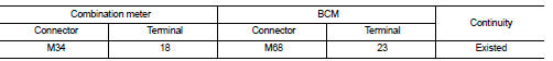
3. Check continuity between combination meter harness connector and ground.
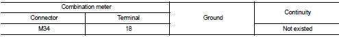
Is the inspection result normal? YES >> Replace combination meter. Refer to MWI-69, "Removal and Installation".
NO >> Repair or replace harness.
 Horn function
Component Function Check
1.CHECK FUNCTION 1
1. Disconnect vehicle security horn relay.
2. Perform ÔÇťVEHICLE SECURITY HORNÔÇŁ in ÔÇťACTIVE TESTÔÇŁ mode of ÔÇťTHEFT ALMÔÇŁ of ÔÇťBCMÔÇŁ
using CONSU ...

Other materials:
Mirrors
Manual anti-glare rearview mirror
Flip the lower adjustment tab forward into the designated night position 1 to significantly dim the harsh reflection and reduce glare caused by the high-beam headlights of trailing vehicles behind you at night.
Push the tab ...
Automatic climate control
(models without Navigation System)
fan speed control dial
intake air control
button
front defroster button
Climate Ctrl. display (dedicated monochromatic status screen for reading target t ...
Electric controlled coupling
Exploded View
1. Filler plug
2. Gasket
3. Drain plug
4. Breather tube
5. Clip
6. Breather hose
7. Breather
8. sub-harness clip
9. sub-harness
10. Rear cover
11. Center stem
12. Side bearing (right)
13. Side bearing adjusting shim (right)
14. Side oil seal (right)
15. Conne ...
