Nissan Juke Service and Repair Manual : ESP off switch
Component Function Check
1.CHECK ESP OFF SWITCH OPERATION
Check that ESP OFF indicator lamp in combination meter turns ON/OFF when ESP OFF switch is operated.
Is the inspection result normal? YES >> INSPECTION END
NO >> Proceed to diagnosis procedure. Refer to BRC-210, "Diagnosis Procedure".
Diagnosis Procedure
1.CHECK ESP OFF SWITCH CIRCUIT
1. Turn the ignition switch OFF.
2. Disconnect ABS actuator and electric unit (control unit) harness connector.
3. Disconnect ESP OFF switch harness connector.
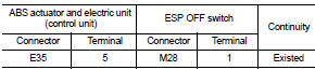
4. Check continuity between ABS actuator and electric unit (control unit) harness connector and ESP OFF switch harness connector.
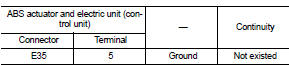
5. Check continuity between ABS actuator and electric unit (control unit) harness connector and ground.
Is the inspection result normal? YES >> GO TO 2.
NO >> Repair or replace error-detected parts.
2.CHECK ESP OFF SWITCH GROUND CIRCUIT
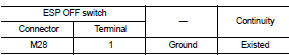
Check continuity between ESP OFF switch harness connector and ground.
Is the inspection result normal? YES >> GO TO 3.
NO >> Repair or replace error-detected parts.
3.CHECK ESP OFF SWITCH
Check ESP OFF switch. Refer to BRC-211, "Component Inspection".
Is the inspection result normal? YES >> GO TO 4.
NO >> Replace ESP OFF switch. Refer to BRC-237, "Removal and Installation".
4.CHECK ESP OFF SWITCH SIGNAL
 With CONSULT-III.
1. Connect ABS actuator and electric unit (control unit) harness connector.
2. Connect ESP OFF switch harness connector.
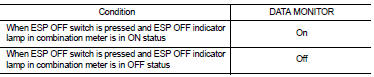
3. Select “ABS”, “DATA MONITOR” and “OFF SW” according to this order. Check ESP OFF switch signal.
Is the inspection result normal? YES >> INSPECTION END
NO >> GO TO 5.
5.CHECK TERMINAL
• Check ABS actuator and electric unit (control unit) pin terminals for damage or loose connection with harness connector.
• Check ESP OFF switch pin terminals for damage or loose connection with harness connector.
Is the inspection result normal? YES >> Replace ABS actuator and electric unit (control unit). Refer to BRC-233, "Removal and Installation".
NO >> Repair or replace error-detected parts.
Component Inspection
1.CHECK ESP OFF SWITCH
1. Turn the ignition switch OFF.
2. Disconnect triple switch harness connector.
3. Check continuity between terminals of ESP OFF switch connector.

Is the inspection result normal? YES >> INSPECTION END
NO >> Replace ESP OFF switch. Refer to BRC-237, "Removal and Installation".
 Parking brake switch
Component Function Check
1.CHECK PARKING BRAKE SWITCH OPERATION
Operate the parking brake lever. Then check that the brake warning lamp in
the combination meter turns ON/
OFF correctly.
Is the ...
 ABS warning lamp
Component Function Check
1.CHECK ABS WARNING LAMP FUNCTION
Check that ABS warning lamp in combination meter turns ON for approx. 1
second after ignition switch is
turned ON.
CAUTION:
Never st ...
Other materials:
Precaution for Disposal
• Before disposing of air bag module, pop-up roll bar and seat belt pre-tensioner,
or vehicles equipped with
such systems, deploy the systems. If such systems have already been deployed due
to an accident, dispose
of them as indicated in Disposing of Air Bag Module, Pop-up Roll Bar and Seat ...
P0200 fuel injector
DTC Logic
DTC DETECTION LOGIC
Diagnosis Procedure
1.CHECK FUEL INJECTOR POWER SUPPLY CIRCUIT FOR OPEN AND SHORT
1. Turn ignition switch OFF.
2. Disconnect ECM harness connector.
3. Disconnect fuel injector harness connector.
4. Check the continuity between fuel injector harness connector an ...
Front disc brake
Brake pad : Inspection and Adjustment
INSPECTION
Check brake pad wear thickness from an inspection hole on cylinder
body. Check using a scale if necessary.
Wear thickness : Refer to BR-71, "Front Disc Brake".
ADJUSTMENT
Burnish contact surfaces between disc rotor and brake pads acc ...
