Nissan Juke Service and Repair Manual : Parking brake switch
Component Function Check
1.CHECK PARKING BRAKE SWITCH OPERATION
Operate the parking brake lever. Then check that the brake warning lamp in the combination meter turns ON/ OFF correctly.
Is the inspection result normal? YES >> INSPECTION END
NO >> Proceed to BRC-208, "Diagnosis Procedure".
Diagnosis Procedure
1.CHECK PARKING BRAKE SWITCH CIRCUIT
1. Turn the ignition switch OFF.
2. Disconnect parking brake switch harness connector.
3. Disconnect combination meter harness connector.
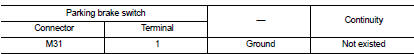
4. Check continuity between parking brake switch harness connector and combination meter harness connector.

5. Check continuity between parking brake switch harness connector and ground.
Is the inspection result normal? YES >> GO TO 2.
NO >> Repair or replace error-detected parts.
2.CHECK PARKING BRAKE SWITCH
Check the parking brake switch. Refer to BRC-208, "Component Inspection".
Is the inspection result normal? YES >> GO TO 3.
NO >> Replace parking brake switch. Refer to PB-5, "Removal and Installation".
3.CHECK COMBINATION METER
Check combination meter. Refer to MWI-23, "CONSULT-III Function".
Is the inspection result normal? YES >> Check each pin terminals for damage or loose connection with harness connector. If any items are damaged, repair or replace error-detected parts.
NO >> Repair or replace combination meter. Refer to MWI-69, "Removal and Installation".
Component Inspection
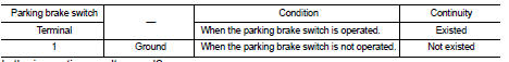
1.CHECK PARKING BRAKE SWITCH
1. Turn the ignition switch OFF.
2. Disconnect parking brake switch harness connector.
3. Check continuity between parking brake switch harness connector.
Is the inspection result normal? YES >> INSPECTION END
NO >> Replace parking brake switch. Refer to PB-5, "Removal and Installation".
 Power supply and ground circuit
Diagnosis Procedure
1.CHECK ABS ACTUATOR AND ELECTRIC UNIT (CONTROL UNIT) IGNITION POWER
SUPPLY
1. Turn the ignition switch OFF.
2. Disconnect ABS actuator and electric unit (control unit) harnes ...
 ESP off switch
Component Function Check
1.CHECK ESP OFF SWITCH OPERATION
Check that ESP OFF indicator lamp in combination meter turns ON/OFF when ESP
OFF switch is operated.
Is the inspection result nor ...
Other materials:
B210C starter control relay
DTC Logic
DTC DETECTION LOGIC
NOTE:
• If DTC B210C is displayed with DTC U1000, first perform the trouble diagnosis
for DTC U1000. Refer to
PCS-30, "DTC Logic".
• When IPDM E/R power supply voltage is low (Approx. 7 - 8 V for about 1
second), the DTC B210C may be
detected.
...
FM-AM-SAT radio with Compact Disc (CD) player (Type A)
1. MUTE button
2. DISP (display)/TEXT button
3. FM·AM radio band select button
4. CD PLAY button
5. Radio station preset buttons
6. iPod® button
7. AUX (auxiliary)/SAT band select button
8. Audio display
9. CLOCK button
10. CD EJECT button
11. iPod® MENU button
12. SEEK/TRACK button
...
Drive information
While in the Drive mode, push the Drive information button to display elapsed
time, average speed and trip distance. Pressing the Drive information button a second
time will display the G (gravity)-Force screen.
Elapsed time
The elapsed time shows the time since the last reset.
Average spee ...
